Method for choosing the defect detection mode of an optical storage device

a technology of optical storage and defect detection mode, applied in the direction of digital signal error detection/correction, instruments, recording signal processing, etc., can solve the problem of absence of related defect records

Inactive Publication Date: 2007-10-11
MEDIATEK INC
View PDF6 Cites 11 Cited by
  • Summary
  • Abstract
  • Description
  • Claims
  • Application Information

AI Technical Summary

Benefits of technology

[0011] The primary objective of the present invention is to provide a method for choosing the defect detection mode of an optical storage device. The defect detection mode is chosen according to the actual locations and densities of defects in an optical storage medium, hence two merits, namely speediness and reliability, concurrently exist.

Problems solved by technology

Furthermore, if the optical storage medium is an unformatted one, related defect records are absent.

Method used


Image

  • Method for choosing the defect detection mode of an optical storage device
  • Method for choosing the defect detection mode of an optical storage device
  • Method for choosing the defect detection mode of an optical storage device

Examples


first embodiment

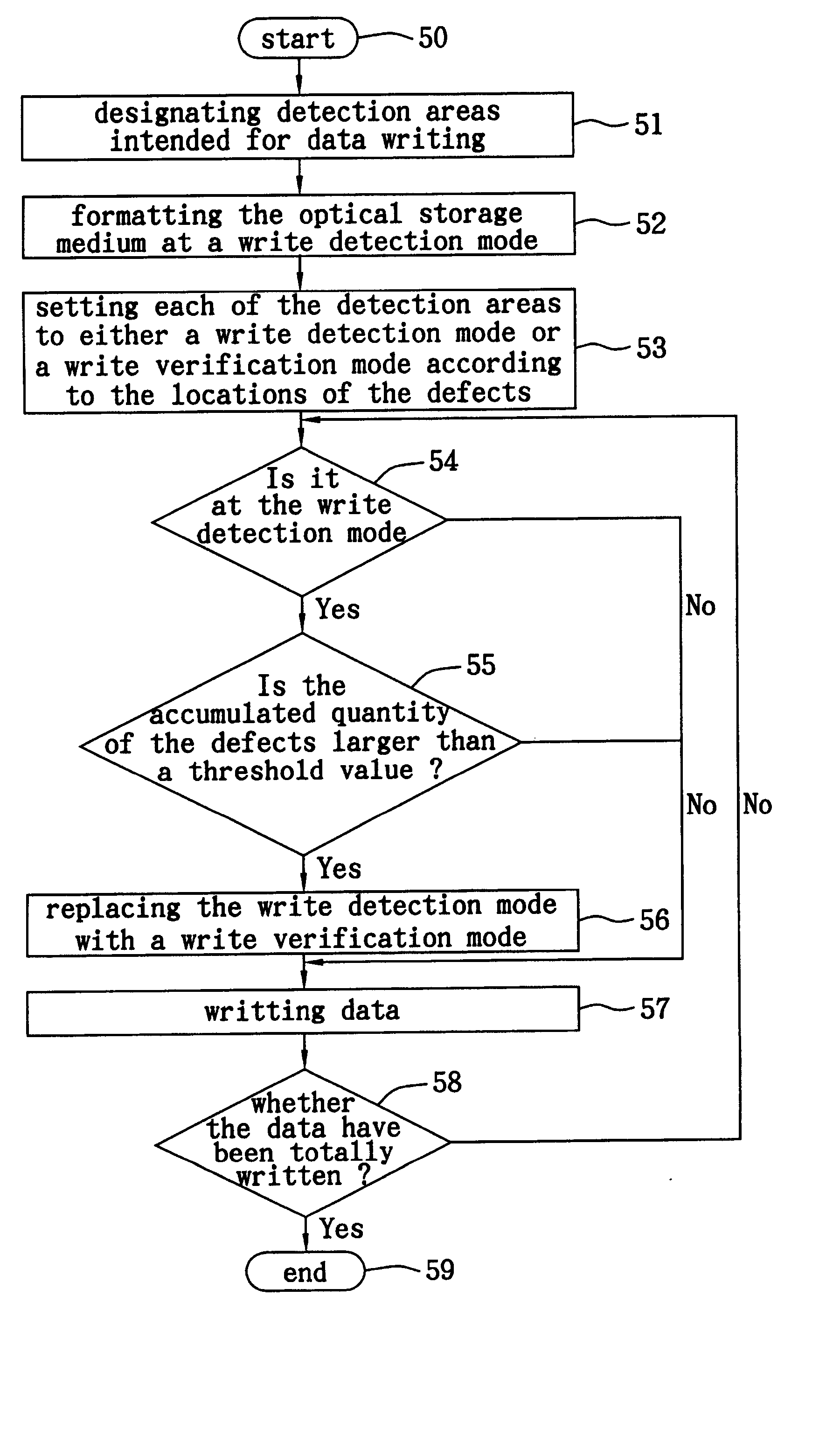
[0023] FIGS. 4(a)-4(c) are schematic diagrams about choosing a defect detection mode in accordance with the present invention. The present preferred embodiment may be applied to a formatted optical storage medium. There are four default detection areas, intended to store data and disposed on the optical storage medium, as shown in FIG. 4(a). The quantity and the locations of the defects in the program area are recorded in a defect table when the optical storage medium is formatted, thus it is possible to know the number of the defects in the detection areas 1-4. The quantity of the defects either in the detection area 1 or in the detection area 4 is smaller than a threshold value; thus both of the detection areas 1 and 4 are set to a write detection mode D first, as shown in FIG. 4(b). The quantity of the defects either in the detection area 2 or in the detection area 3 is greater than the threshold value; thus both of the detection areas 2 and 3 are initially set to a write verific...

second embodiment

[0026] FIGS. 6(a)-6(b) are schematic diagrams about choosing a defect detection mode in accordance with the present invention. The present preferred embodiment may be applied to an optical storage medium which is unformatted or whose defect distribution remains unknown. Assuming eight detection areas intended for data storage are disposed on the optical storage medium, as shown in FIG. 6(a), it is impossible to know the number of the defects in the detection areas 1 through 8 since the optical storage medium has not yet been formatted. It is expedient to set all the detection areas to the write detection mode D first. If it is found from the detection areas 2, 3 and 7 that the respective accumulated quantity of defects is greater than a threshold value within the duration of a data writing operation and defect detection operation, the corresponding detection area would be changed from the write detection mode D to the write verification mode V, as shown in FIG. 6(b).

[0027]FIG. 7 is ...


PUM

PropertyMeasurementUnit
intrinsic structural defectaaaaaaaaaa
defect detectionaaaaaaaaaa
defectaaaaaaaaaa

Abstract

At least one detection area on an optical storage medium is allocated for data storage first, and then the detection area is set to a defect detection mode of either write detection or write verification, depending on the number of defects stated in a previous defect record. If the detection area is the write detection mode and the number of accumulated defects exceeds a default threshold value, the detection area would be configured anew and thereby set to a defect detection mode of write verification.

Description

CROSS REFERENCE TO RELATED APPLICATIONS [0001] This application is a divisional application of U.S. application Ser. No. 10 / 904,886 field Dec. 2, 2004, and is based on and claims priority from Taiwanese Patent Application No. 093108873 filed Mar. 31, 2004.BACKGROUND OF THE INVENTION [0002] 1. Field of the Invention [0003] The present invention relates to a method for choosing the defect detection mode of an optical storage device, more particularly to a method for choosing the defect detection mode of an optical storage device before data are recorded on an optical storage medium. [0004] 2. Description of the Related Art [0005] In the event of the existence of defects, for example, scratches, contamination and an intrinsic structural defect, in parts of an optical storage medium (such as a CD), predetermined data cannot be correctly stored on the parts of the optical storage medium. An attempt to read the stored data always ends in finding the data not retrievable and therefore not ...

Claims


Application Information

Patent Timeline
Patent Type & Authority Applications(United States)
IPC IPC(8): G11B15/52G11B5/09G11B7/0045G11B20/18
CPCG11B20/18G11B7/00458
Inventor JIN, KUO-WENTSAI, SHOU-RENYAU, WEI-GUAN
Owner MEDIATEK INC
Why Eureka
Try Eureka