Optical recording medium

a recording medium and optical technology, applied in mechanical recording, instruments, natural mineral layered products, etc., can solve the problems of sporadically coming into contact with optical pickup lenses, slow access time for reproducing information from optical recording mediums, and inability to accurately reproduce information, so as to reduce the working distance between optical pickup and optical recording mediums. , the numerical aperture of the objective lens is increased

Inactive Publication Date: 2000-05-16
SONY CORP
View PDF3 Cites 42 Cited by
  • Summary
  • Abstract
  • Description
  • Claims
  • Application Information

AI Technical Summary

Benefits of technology

Accordingly, it is an object of the invention to provide an improved optical recording medium in which the thickness of the light transmissive layer thereof is reduced in order to allow for

Problems solved by technology

If this working distance is not reduced, and a working distance similar to that of a conventional objective lens is used, the objective lens must be very large and heavy, and as a result, the access time for reproducing information from the optical recording medium is slow and the tracking servo and focus servo are less exact.
However, when this working distance is reduced, it is thereafter possible that the optical pickup lens will sporadically come into contact and collide with the optical recording medium.
Therefore, when the optical pickup collides with the optical recording medium, it is possible that the optical recording medium will be broken.
Additionally, if the objective lens of the optical pickup collides with the optical recording medium, the light transmissive layer may be easily scratched or deformed, since the plastic (such as polycarbonate, UV curable resin, or the like) which forms a transparent disc substrate or light transmissive layer is a very soft material as compared with the glass forming the objective lens.
Therefore, the objective lens may crack the transparent disc substrate, or scratch the surface of the light transmissive layer.
Since information is reproduced from the recording medium via the irradiation of light, any scratches in the surface thereof may disrupt the light path, and therefore reduce the effectiveness of the reproduction of the information from the optical recording medium.
It is possible that the plastic of the holder for the objective lens may scratch the recording medium, if the plastic forming the obje

Method used


Image

  • Optical recording medium
  • Optical recording medium
  • Optical recording medium

Examples


example 2

In Example 2, the relationship between the thickness of first layer 414 of light transmissive layer 412 and the occurrence of scratches on the surface thereof was surveyed. Optical recording media having a diameter of 60 nm and having a second layer 415 formed of an ultraviolet curing resin were prepared. A first group of the recording media were formed with a first layer 414 formed of SiO.sub.2, deposited, by sputtering, having thicknesses of 1 nm, 2 nm, 10 nm, 50 nm and 200 nm, respectively. A second group of optical recording media were formed with first layer 414 formed of Si.sub.3 N.sub.4, deposited by sputtering, having thicknesses of 1 nm, 2 nm, 10 nm, and 50 nm, respectively. Table 2 below shows the results of the test performance, indicating the degree of scratches formed on particular recording media.

As is shown in Table 2, regardless of the kind of material used to form first layer 414, as the thickness of first layer 414 increases, the number of scratches thereon decreas...

##ivity examples

Reflectivity Examples

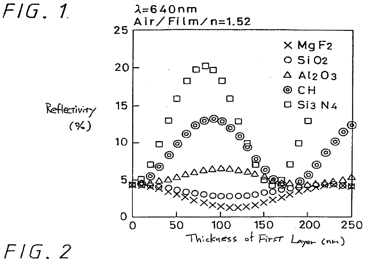
Reference is next made to FIG. 1 which depicts the calculated reflectivity of an irradiated light beam having a wavelength of 640 nm from an optical recording medium. Second layer 415 of light transmissive layer 412 is formed of a UV resin without fluoride and having an index of refraction relative to the air fixed at a value of 1.52. Various materials were tested, including MgF.sub.2, FiO.sub.2, Al.sub.2 O, CH and Si.sub.3 N.sub.4 having refractivities of 1.38, 1.46, 1.60, 1.80 and 2.00, respectively. In FIG. 1, the X axis indicates the thickness of first layer 414, while the Y axis indicates the reflectivity thereof.

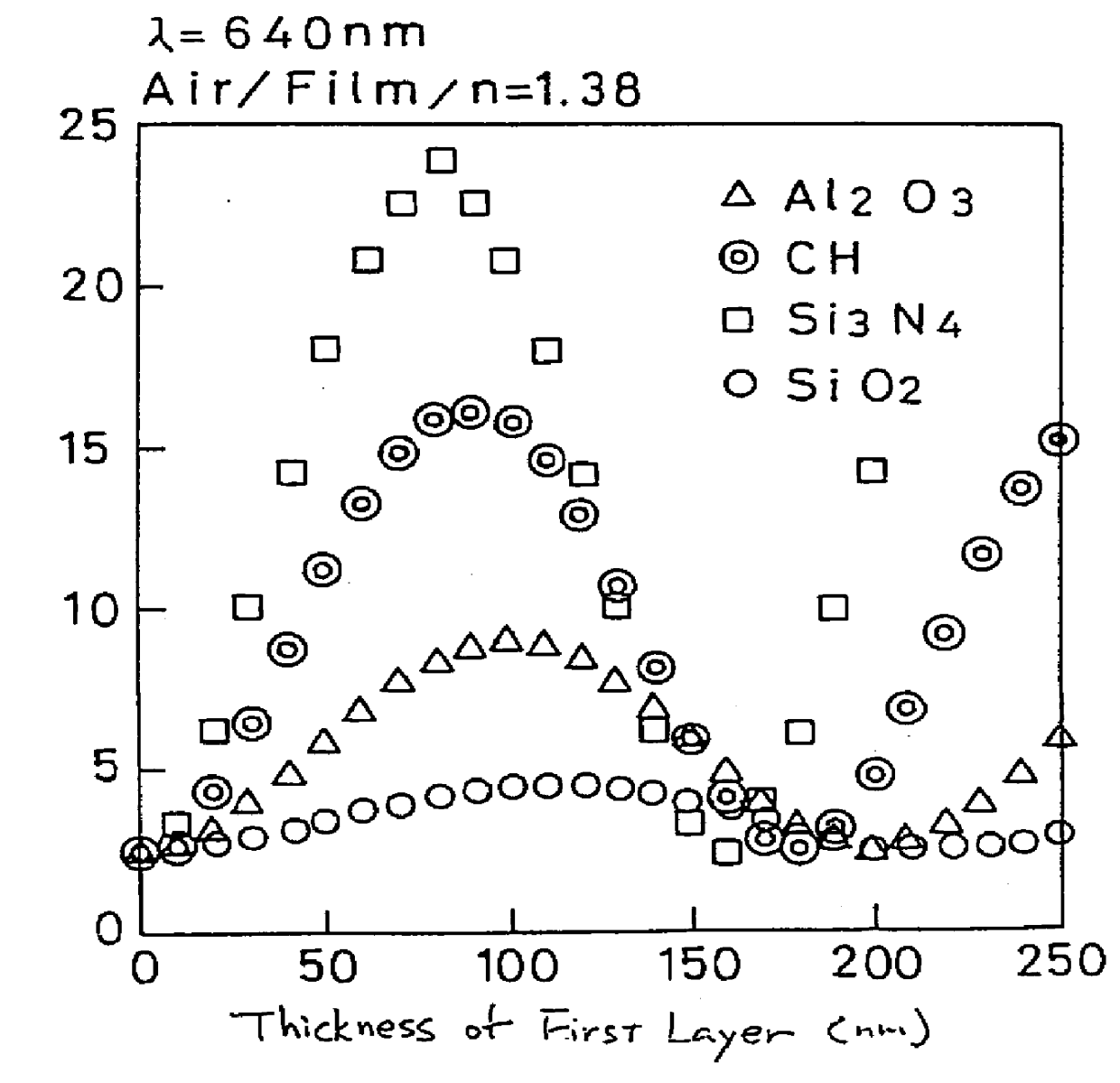
FIG. 2 depicts a similar graph, using similar materials to form first layer 414, but wherein the second layer 415 of light transmissive layer 412 is formed of a UV resin with fluoride, and thus having an index of refraction relative to air fixed at a value of 1.38, rather than 1.52 shown in FIG. 1.

The reflectivity of an ordinary polycarbonate trans...

first embodiment

In accordance with alternative embodiments of the invention the first, surface layer may be formed of other materials. The inventors have determined that if first, surface layer 414 is formed of SiN, by sputtering, the optimal thickness is approximately 100 nm. This thickness is determined similarly to the determination of thickness in the first-described embodiment. Indeed, any suitable material may be used to form the first, surface layer of the light transmissive layer, as long as this material has a Young's modulus of greater than 70 GPa, and preferably greater than 150 GPa, and also gives the optical recording medium a sufficient pencil hardness, such as at least H, or more preferably 2H. The optimum thickness of the layer of material should be determined in each case in accordance with the procedure set forth with respect to the Using such a material assures that in the event of a collision of an objective lens with the surface of the optical recording medium, a scratch will ...


PUM

PropertyMeasurementUnit
Thicknessaaaaaaaaaa
Thicknessaaaaaaaaaa
Pressureaaaaaaaaaa

Abstract

An improved optical recording medium is provided, and includes a surface of the optical recording medium having at least pits and grooves formed therein, a recording layer formed adjacent the surface of said optical recording medium, and a light transmissive layer formed adjacent the recording layer. Information is recorded and/or reproduced by irradiation of light from an optical pickup employing an objective lens having a numerical aperture of 0.7 or larger through the light transmission layer. At least a surface layer of said light transmissive layer is formed of a material having a Young's modulus of 70 GPa or larger thereby greatly reducing or eliminating scratches from the surface of the optical recording medium while allowing for an increase in the storage capacity of the optical storage medium.

Description

This invention relates generally to an optical recording medium and more particularly to an optical recording medium having a reduced thickness and an increased hardness in order to improve the information storage density thereof, and to defend against damage resulting from contact with an optical lens or the like. Most recently, optical recording media have become very important in the recording medium industry, and therefore various studies and much research concerning optical information recording systems for recording information on, and retrieving information from, optical recording media have taken place. An optical information recording system has various advantages, including information being recorded and reproduced without contact between the optical reading / recording head and the recording medium, a higher recording density being achieved as compared with magnetic recording medium, and the optical information recording system being applied to a system allowing for read on...

Claims


Application Information

Patent Timeline
IPC IPC(8): G11B7/254G11B7/24G11B7/24035G11B7/24038G11B7/24056G11B7/2548
CPCG11B7/252G11B7/2548G11B2007/25414Y10T428/21Y10S428/913Y10S430/146G11B2007/25417
Inventor ARATANI, KATSUHISAKASHIWAGI, TOSHIYUKIKIKUCHI, MINORU
Owner SONY CORP
Why Eureka
Try Eureka