Filter with memory, communication and temperature sensor

Inactive Publication Date: 2007-10-18
MILLIPORE CORP
View PDF70 Cites 50 Cited by
  • Summary
  • Abstract
  • Description
  • Claims
  • Application Information

AI Technical Summary

Benefits of technology

[0009] The use of this device is beneficial to many applications. For example, the ability to read filter temperatures in situ allows improved Sterilization-

Problems solved by technology

Despite the improvements that have occurred through the use of RFID tags, there are additional areas that have not been satisfactorily addressed.
C

Method used


Image

  • Filter with memory, communication and temperature sensor
  • Filter with memory, communication and temperature sensor

Examples


Embodiment Construction

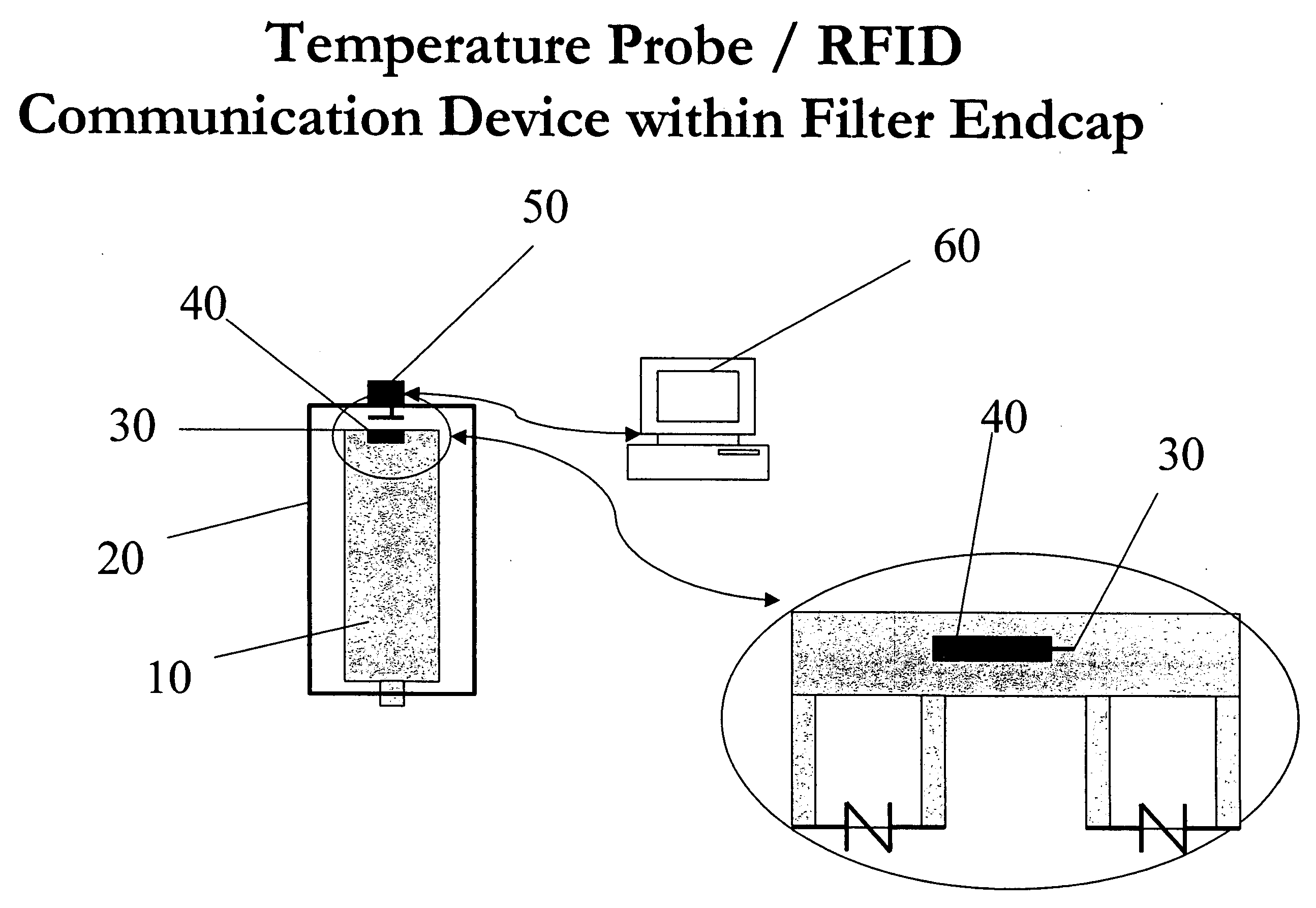
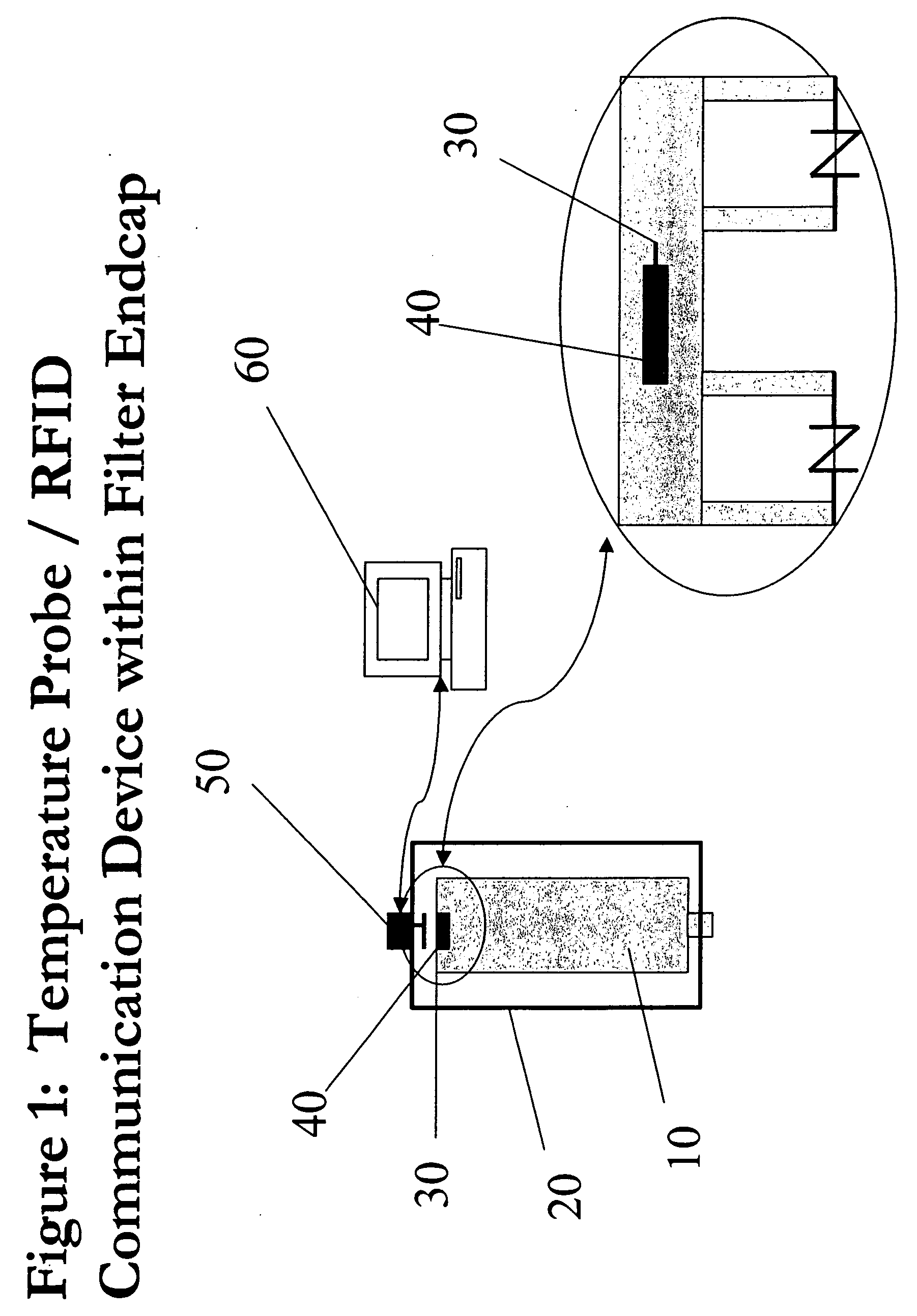
[0011]FIG. 1 illustrates a representative filtering system in accordance with the present invention. The filter element 10 is enclosed with a housing 20. The filter element can be simply a porous material, such as pleated paper or PVDF (Polyvinylidene fluoride) membrane. Alternatively, the filter element may comprise a frame, such as of plastic, and a porous material. Located in close proximity of, and preferably embedded in, the filter element 10 is a temperature sensor 30. This sensor 30 is capable of generating an output, which varies as a function of the surrounding temperature. This output can be in the form of an analog voltage or current, or can be a digital value. In the preferred embodiment, the output varies linearly with temperature, however this is not a requirement. Any output having a known relationship, such as logarithmic or exponential, to the surrounding temperature, can be employed. In such a situation, a transformation of the output can be performed to determine ...


PUM

PropertyMeasurementUnit
Temperatureaaaaaaaaaa
Pressureaaaaaaaaaa

Abstract

The present invention describes a system and method for accurately measuring the temperature of a filter element. A temperature transducer, and a communications device are coupled so as to be able to measure and transmit the temperature of a filter element while in use. This system can comprise a single component, integrating both the communication device and the temperature transducer. Alternatively, the system can comprise separate temperature transducer and transmitter components, in communication with one another. In yet another embodiment, a storage element can be added to the system, thereby allowing the device to store a set of temperature values. The use of this device is beneficial to many applications. For example, the ability to read filter temperatures in situ allows improved Sterilization-In-Place (SIP) protocol compliance, since the temperatures of actual filter elements can be directly measured, rather than interpolated as is done currently.

Description

BACKGROUND OF THE INVENTION [0001] The use of RFID tags has become prevalent, especially in the management of assets, particularly those applications associated with inventory management. For example, the use of RFID tags permits the monitoring of the production line and the movement of assets or components through the supply chain. [0002] To further illustrate this concept, a manufacturing entity may adhere RFID tags to components as they enter the production facility. These components are then inserted into the production flow, forming sub-assemblies in combination with other components, and finally resulting in a finished product. The use of RFID tags allows the personnel within the manufacturing entity to track the movement of the specific component throughout the manufacturing process. It also allows the entity to be able to identify the specific components that comprise any particular assembly or finished product. [0003] In addition, the use of RFID tags has also been advocate...

Claims


Application Information

Patent Timeline
IPC IPC(8): B01D46/00
CPCB01D29/114B01D35/143B01D46/429B01D46/448A61L2/28B01D2201/291B01D2201/54B01D2201/56A61L2/07B01D46/46
Inventor DILEO, ANTHONY
Owner MILLIPORE CORP
Why Eureka
Try Eureka