Autofeed mechanism for heated humidifier chamber

a technology of automatic feeding and humidifier chamber, which is applied in the direction of operating means/releasing devices of valves, heating types, lighting and heating apparatus, etc., can solve the problems of inability to accurately control the level of the humidifier chamber, the reliance on a lever almost constantly submerged and at least one location is not suitable for critical applications, and the float-and-lever control device is not particularly well suited to miniaturization to small-scale applications

Inactive Publication Date: 2007-10-18
CAREFUSION 2200 INC
View PDF8 Cites 27 Cited by
  • Summary
  • Abstract
  • Description
  • Claims
  • Application Information

AI Technical Summary

Benefits of technology

[0006] In its most general configuration, the present invention advances the state of the art with a variety of new capabilities and overcomes many of the shortcomings of prior devices in new and novel ways. In its most general sense, the present invention overcomes the shortcomings and limitations of the prior art in any of a number of generally effective configurations. The instant invention demonstrates such capabilities and overcomes many of the shortcomings of prior methods in new and novel ways.

Problems solved by technology

Such float-and-lever control devices appear relatively simple, yet as any homeowner knows, are plagued with problems.
Additionally, float-and-lever control devices are not particularly well suited for miniaturization to small-scale application.
Further, the level of control offered is relatively crude and not suitable for applications requiring precise level control.
Still further, its reliance on an almost constantly submerged lever that must pivot in at least one location is not appropriate for critical applications.
Still, many such untethered designs suffered from large size requirements and were not suitable for critical applications.

Method used


Image

  • Autofeed mechanism for heated humidifier chamber
  • Autofeed mechanism for heated humidifier chamber
  • Autofeed mechanism for heated humidifier chamber

Examples


Embodiment Construction

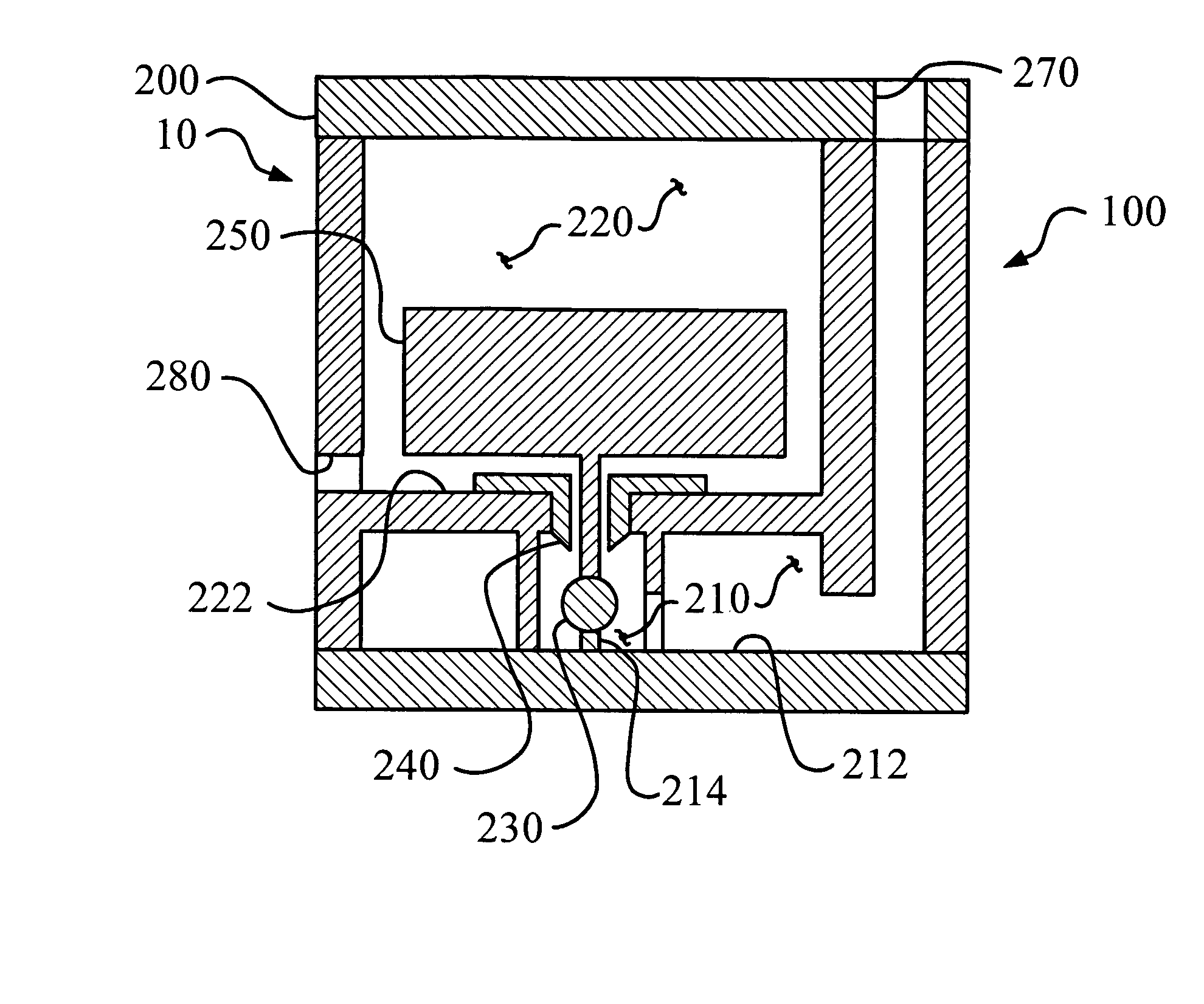
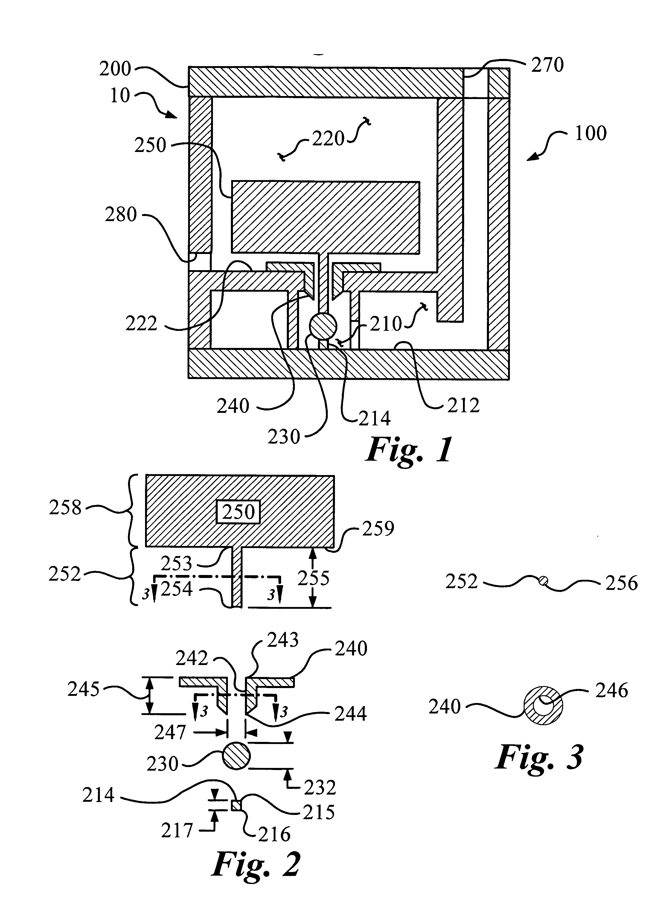
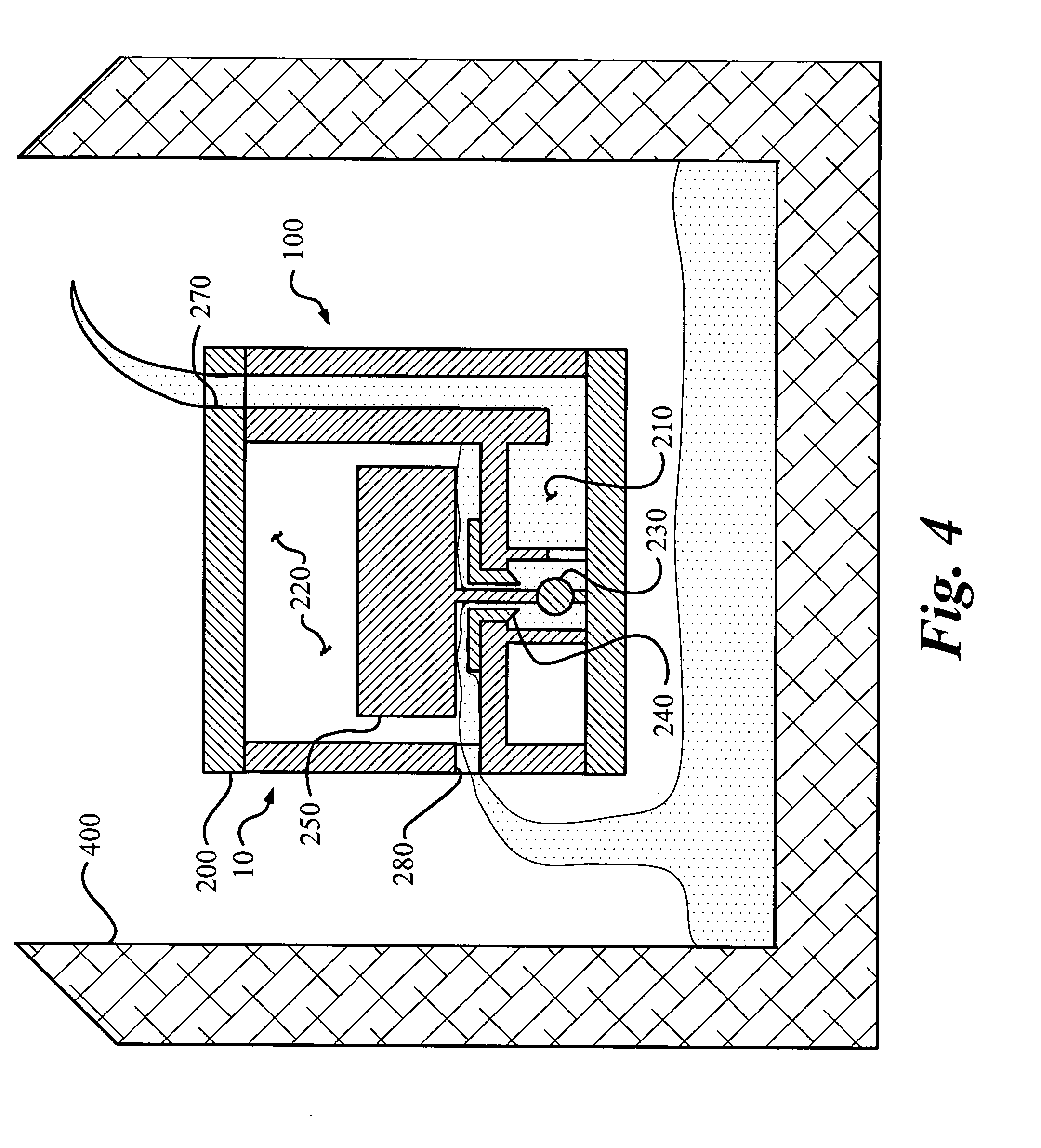
[0029] The autofeed mechanism for a heated humidifier chamber (10) of the instant invention enables a significant advance in the state of the art. The preferred embodiments of the apparatus accomplish this by new and novel arrangements of elements that are configured in unique and novel ways and which demonstrate previously unavailable but preferred and desirable capabilities. The detailed description set forth below in connection with the drawings is intended merely as a description of the presently preferred embodiments of the invention, and is not intended to represent the only form in which the present invention may be constructed or utilized. The description sets forth the designs, functions, means, and methods of implementing the invention in connection with the illustrated embodiments. It is to be understood, however, that the same or equivalent functions and features may be accomplished by different embodiments that are also intended to be encompassed within the spirit and s...


PUM


Abstract

An autofeed mechanism for controlling the flow and level of a fluid. The mechanism includes a body with an inlet chamber and a float chamber. A seat permits fluid communication between the two chambers. A float and a ball cooperate to permit, or deny, access to the seat. Fluid first enters the inlet and fills the chamber and then enters the float chamber by passing through the seat and exiting via the exit. Initially, the weight of the float keeps the ball away from the seat, but eventually the fluid level rises high enough that the action of the float on the ball decreases to a level that is overcome by the buoyant force of the ball and other fluidic forces resulting in the ball moving away from the ball support. Finally, the ball rises enough to seal against the seat thus stopping the flow of fluid.

Description

TECHNICAL FIELD [0001] The present invention generally relates to an automatic flow and level control device, especially for an autofeed mechanism particularly suited for controlling the fluid level in a heated humidifier chamber. BACKGROUND OF THE INVENTION [0002] Automatic flow control devices have been around for hundreds, if not thousands, of years. A large portion of automatic flow control devices are dedicated to maintaining a predetermined fluid level in a reservoir, or tank. Such level maintaining automatic flow control valves have often incorporated elements that float on the surface of the fluid to indicate when the desired fluid level has been obtained. Perhaps the most famous level maintaining automatic flow control valve is that found in the storage tank of a water closet, or toilet. The water closer tank control valve includes a float mounted on a lever that is connected to a shut-off device in the water supply line. When the water in the tank rises to the desired leve...

Claims


Application Information

Patent Timeline
Patent Type & Authority Applications(United States)
IPC IPC(8): F16K31/18
CPCA61M16/1075A61M16/162A61M16/167F24F6/02F16K31/20A61M16/168Y10T137/0318Y10T137/6579Y10T137/7404Y10T137/742Y10T137/7426
Inventor RUSTAD, ANDREHALPERIN, SCOTT
Owner CAREFUSION 2200 INC
Why Eureka
Try Eureka