Heat exchanger

a heat exchanger and heat exchange medium technology, applied in indirect heat exchangers, lighting and heating apparatus, stationary conduit assemblies, etc., can solve the problems of severe temperature difference between the right and left sides of the heat exchanger, inability to provide a secure control, and deterioration of the mixing performance of the heat exchange medium, so as to reduce the operating force and increase the durability

Inactive Publication Date: 2007-10-18
HANON SYST
View PDF10 Cites 9 Cited by
  • Summary
  • Abstract
  • Description
  • Claims
  • Application Information

AI Technical Summary

Benefits of technology

[0016]Accordingly, the present invention has been made to solve the above-mentioned problems occurring in the prior arts, and it is an object of the present invention to provide a heat exchanger, which can independently controls the volume of heat exchange medium flowing through tubes of a left heat exchange part and a right heat exchange part to independently control the temperature of a driver's seat and a passenger's seat, thereby realizing a compact structure since a temp door for controlling temperature is omitted from an air-conditioning system for the vehicle, which can reduce an operating force and increase durability since heat exchange medium controlling means are in a rotational structure, and which can minimize a temperature difference between the right and left sides thereof since the heat exchange medium is distributed to the tubes uniformly.

Problems solved by technology

However, to control the heat exchange capacity by adjusting the volume of air needs a separate device, it cannot provide a secure control.
The heat exchanger can selectively adjust the volume of the heat exchange medium, but has several problems in that a mixing performance of the heat exchange medium is deteriorated and there is a severe temperature difference in right and left temperature between the right and left sides of the heat exchanger since the heat exchange medium guided by the blocking vane 27 of the rotating member 23 is concentrated on tube arrays of one side of the heat exchanger.
In addition, the conventional heat exchanger has another problem in that temperature of a driver's seat and temperature of a passenger's seat cannot be controlled separately since temperature control is applied to the whole of the heat exchanger.

Method used


Image

  • Heat exchanger
  • Heat exchanger
  • Heat exchanger

Examples


Embodiment Construction

[0027]Reference will be now made in detail to the preferred embodiment of the present invention with reference to the attached drawings.

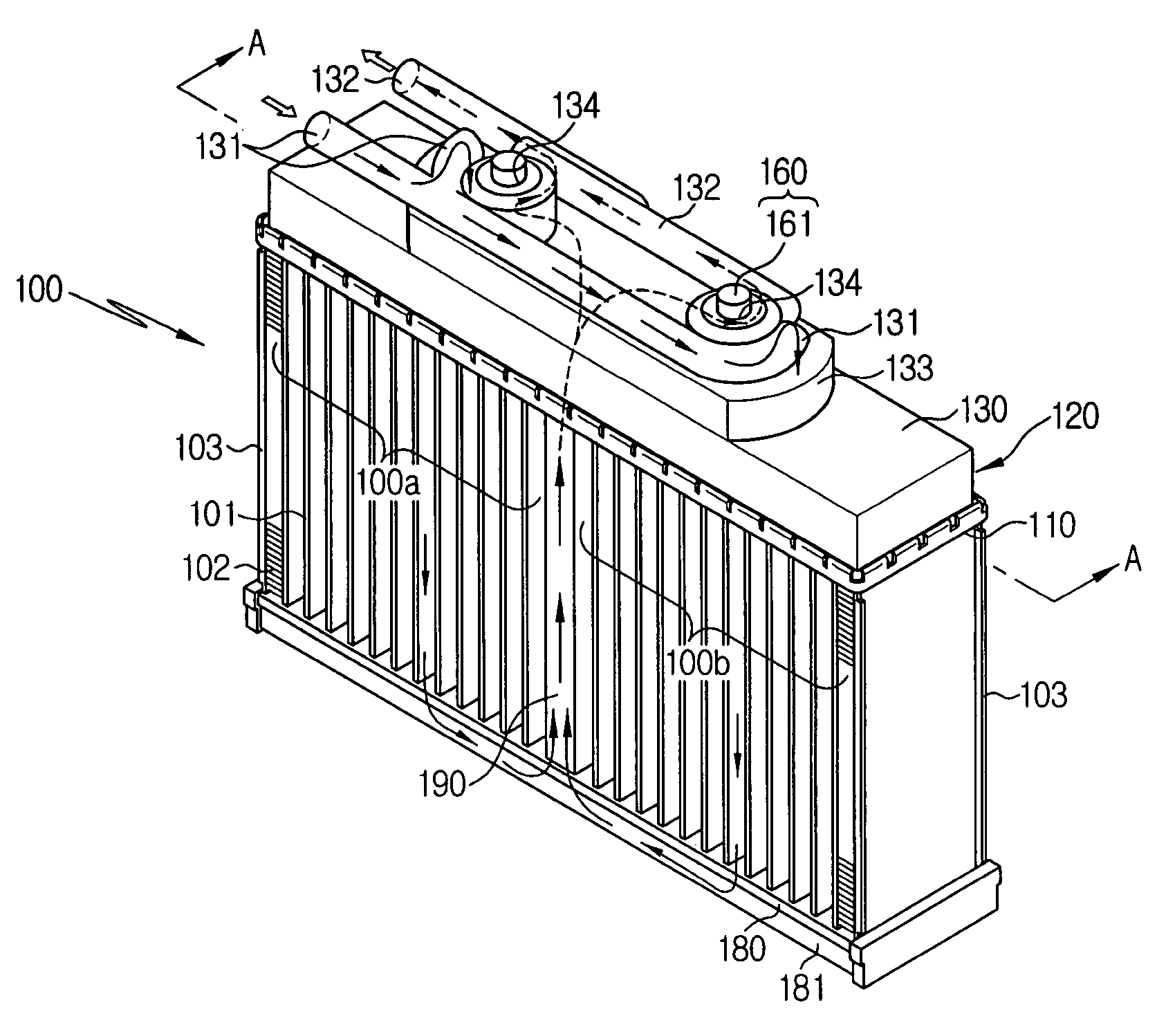
[0028]FIG. 4 is a perspective view of a heat exchanger according to the present invention, FIG. 5 is an exploded perspective view of the heat exchanger according to the present invention, FIG. 6 is a sectional view taken along the line of A-A of FIG. 4, FIG. 7 is a sectional view showing a state where a partitioning wall of a return pipe of FIG. 6 is omitted, and FIGS. 8 to 10 are plan views illustrating a flow of heat exchange medium according to an operational state of a heat exchange medium controlling means in the heat exchanger according to the present invention.

[0029]As shown in the drawings, the heat exchanger 100 according to the present invention includes a plurality of tubes 101 for allowing a flow of heat exchange medium, the tubes being arranged at regular intervals and having ends combined to an upper header 110 and a lower header 180.

[...


PUM


Abstract

The present invention relates to a heat exchanger, which can independently controls the volume of heat exchange medium flowing through tubes of a left heat exchange part and a right heat exchange part to independently control the temperature of a driver's seat and a passenger's seat, thereby realizing a compact structure since a temp door for controlling temperature is omitted from an air-conditioning system for the vehicle, which can reduce an operating force and increase durability since heat exchange medium controlling means are in a rotational structure, and which can minimize a temperature difference between the right and left sides thereof since the heat exchange medium is distributed to the tubes uniformly.

Description

BACKGROUND OF THE INVENTION[0001]1. Field of the Invention[0002]The present invention relates to a heat exchanger, and more particularly, to a heat exchanger, which can independently controls the volume of heat exchange medium flowing through tubes of a left heat exchange part and a right heat exchange part to independently control the temperature of a driver's seat and a passenger's seat, thereby realizing a compact structure since a temp door for controlling temperature is omitted from an air-conditioning system for the vehicle, which can reduce an operating force and increase durability since heat exchange medium controlling means are in a rotational structure, and which can minimize a temperature difference between the right and left sides thereof since the heat exchange medium is distributed to the tubes uniformly.[0003]2. Background Art[0004]In general, an air conditioner includes a cooling system and a heating system. The cooling system cools the inside of a vehicle by heat e...

Claims


Application Information

Patent Timeline
Patent Type & Authority Applications(United States)
IPC IPC(8): F28F27/02
CPCF28D1/05366F28D2001/0266F28F2250/06F28D2021/0096F28F27/02F28D2021/0085F28F9/22F28F9/00F28F27/00
Inventor HAN, SEONGSEOK
Owner HANON SYST
Why Eureka
Try Eureka