Break-apart conduit bracket sheet

Inactive Publication Date: 2007-10-18
KOPP JOHN GORDON
View PDF21 Cites 6 Cited by
  • Summary
  • Abstract
  • Description
  • Claims
  • Application Information

AI Technical Summary

Benefits of technology

[0011] A still further objective is to provide a set of identical units easily broken away from each oth

Problems solved by technology

However there does not appear in the prior art to be a

Method used


Image

  • Break-apart conduit bracket sheet
  • Break-apart conduit bracket sheet
  • Break-apart conduit bracket sheet

Examples


Embodiment Construction

[0020] The above described drawing figures illustrate the described apparatus and its method of use in at least one of its preferred, best mode embodiment, which is further defined in detail in the following description. Those having ordinary skill in the art may be able to make alterations and modifications what is described herein without departing from its spirit and scope. Therefore, it should be understood that what is illustrated is set forth only for the purposes of example and that it should not be taken as a limitation in the scope of the present apparatus and method of use.

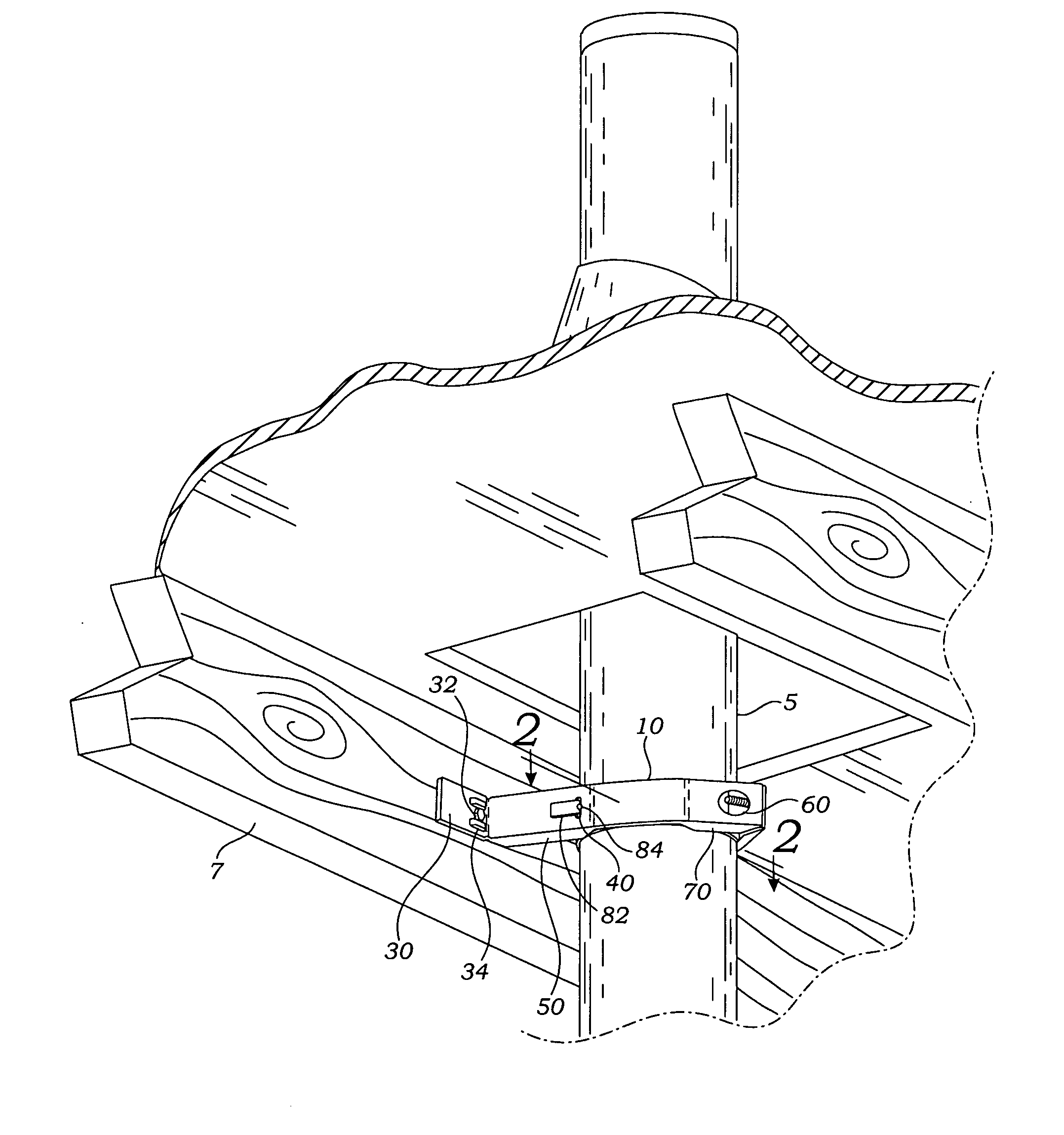
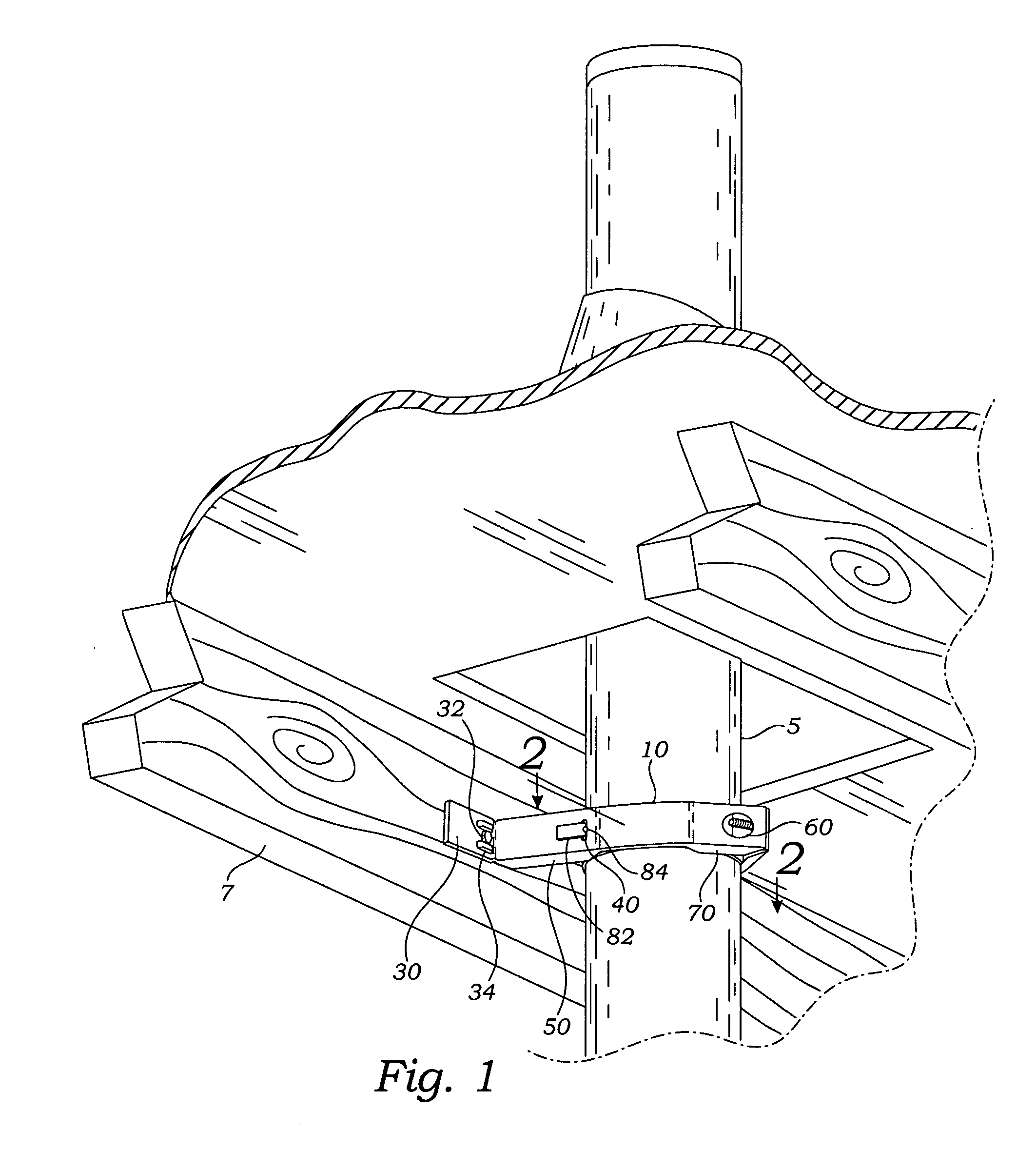
[0021] Described now in detail is the preferred embodiment of the present bracket apparatus and method of its use. Strap units 10 are able to secure a pipe, flue, conduit 5 to a support surface 7 as shown in FIG. 1. Although the strap units 10 may be fabricated individually, the preferred mode is to fabricate them in groups from a single piece of sheet material as shown in FIGS. 3 and 4. In FIG. 3 is sh...


PUM


Abstract

A plurality of brackets formed as straps from a single piece of sheet material are useful for supporting pipes, vents, flues and similar articles. The straps are mutually joined in side-by-side positions by frangible tabs so that they are easily broken apart, one from the other, by manual bending of the frangible tabs. Each of the straps provides, at each one of its opposing ends, in spaced apart sequence, starting at the terminal ends and moving medially along the straps, features formed in the sheet material, including: a mounting hole for receiving a fastener, a slot for receiving a tab, a fastener access hole, and a tab.

Description

BACKGROUND OF THE INVENTION [0001] 1. Field of the Present Disclosure [0002] This disclosure relates generally to the support of pipes in general and exhaust flue pipes and vents in particular, and more specifically to an apparatus providing connected but easily broken apart sheet metal strips that are easily formed into a strap-like bracket facilitating the securement of such conduits. [0003] 2. Description of Related Art Including Information Disclosed Under 37 CFR 1.97 and 1.98 [0004] Reynoso, U.S., Des 257947 discloses a design for a bracket for mounting a heater vent pipe between joists and rafters. Williamson, U.S. Pat. No. 851,720 discloses a flue support consisting of two parallel spaced U-shaped metal straps having their extremities turned outwardly at right angles in a common plane, and a pair of independently formed parallel spaced cross-straps, disposed upon the web portions of the U-shaped straps and having their ends turned downwardly against the outer edges of the web...

Claims


Application Information

Patent Timeline
IPC IPC(8): F16L3/08F23J13/02
CPCF23J2213/101F16L3/137
Inventor KOPP, JOHN GORDON
Owner KOPP JOHN GORDON
Why Eureka
Try Eureka