Compact mechanical seal

a mechanical seal and compact technology, applied in the field of mechanical seals, can solve the problems of shortened lift span, oil leakage, worn rubber lip and rotary shaft, etc., and achieve the effect of improving the sealing

Inactive Publication Date: 2007-10-18
KIM HAN SIK
View PDF7 Cites 18 Cited by
  • Summary
  • Abstract
  • Description
  • Claims
  • Application Information

AI Technical Summary

Benefits of technology

[0006]The present invention has been made in view of the above-mentioned problems incurred in the related art, and an object of the invention is to provide a mechanical seal having a compact structure so that it can be installed in a limited space while obtaining an enhanced sealing effect.

Problems solved by technology

Since the rubber lip directly contacts the rotary shaft in the conventional oil seal, the rubber lip and rotary shaft may be worn.
As a result, there are drawbacks of oil leakage and shortened lift span.
However, conventional mechanical seals have a drawback of an increased installation space.

Method used


Image

  • Compact mechanical seal
  • Compact mechanical seal
  • Compact mechanical seal

Examples


Embodiment Construction

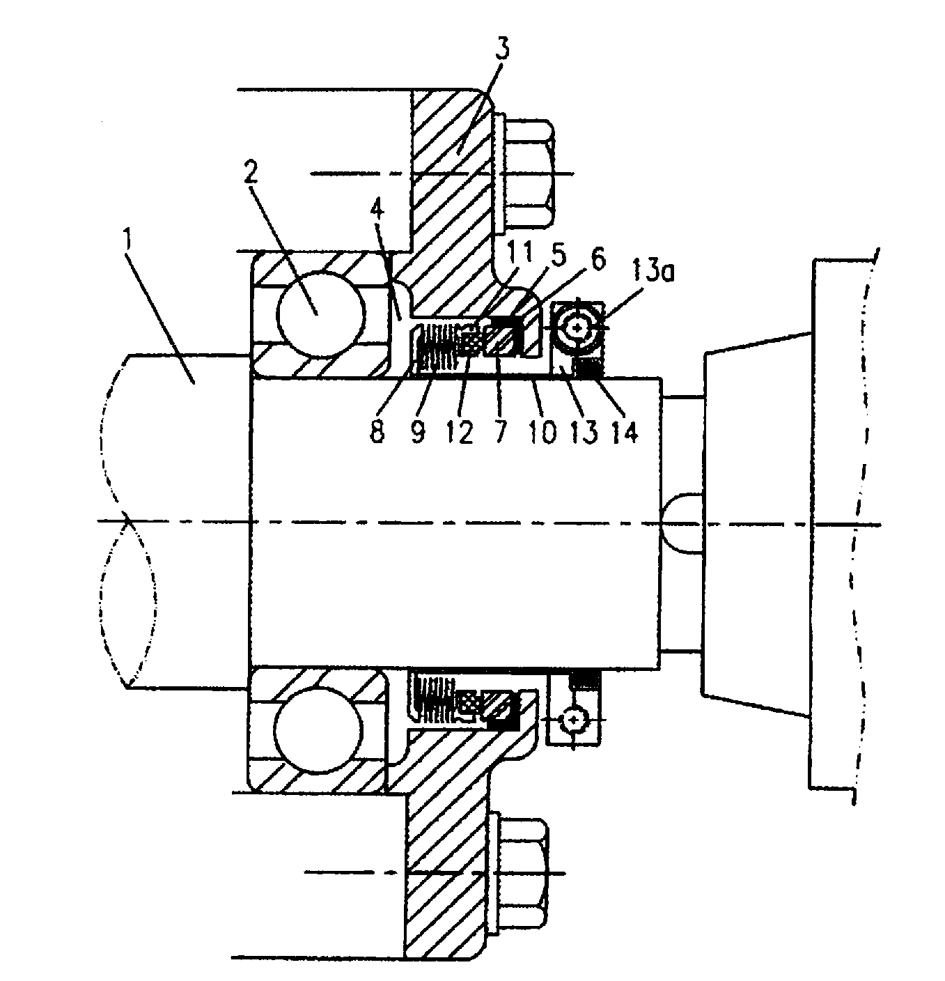
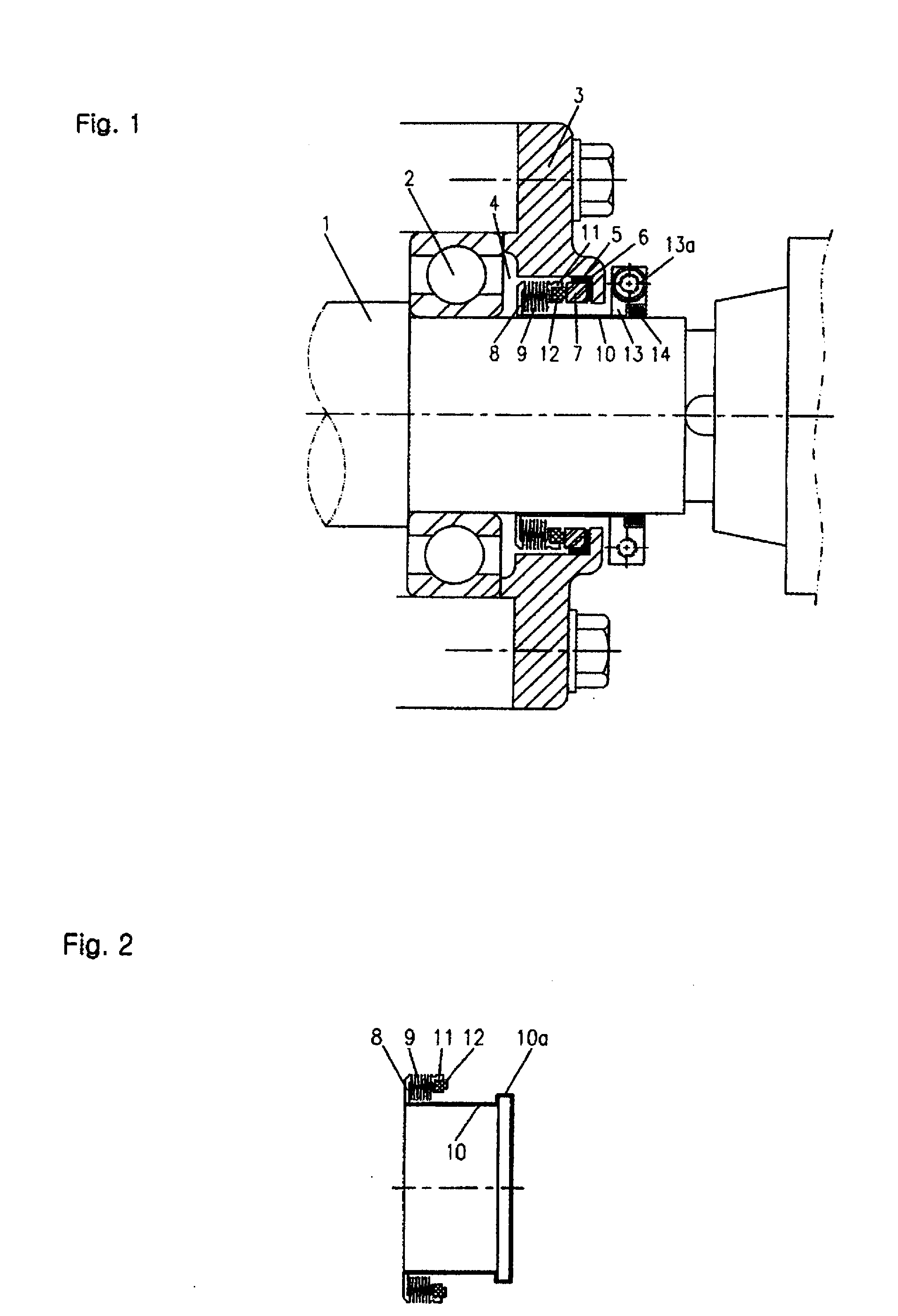
[0021]Referring to FIG. 1, a compact mechanical seal according to an embodiment of the present invention is illustrated.

[0022]As shown in FIG. 1, the compact mechanical seal includes a stationary seal part fitted around a rotary shaft 1 such that the stationary seal part is maintained in a stationary state when the rotary shaft 1 rotates, and a rotary seal part fitted around the rotary shaft 1 such that the rotary seal part is rotated together with the rotary shaft 1 when the rotary shaft 1 rotates.

[0023]The stationary seal part of the compact mechanical seal includes an oil seal cover 3 mounted to a bearing housing fitted around the rotary shaft 1, a rubber packing 6 fixed to an inner surface of the oil seal cover 3, and a stationary seal ring 7 fixed to the rubber packing 6. The stationary seal ring 7 provides an annular stationary seal face.

[0024]The rotary seal part includes a sleeve 10 tightly fitted around the rotary shaft 1, a spring support 8 fixed to one end of the sleeve 1...


PUM


Abstract

A mechanical seal having a compact structure is disclosed. The mechanical seal includes a stationary seal part fitted around a rotary shaft such that the stationary seal part is maintained in a stationary state when the rotary shaft rotates, and a rotary seal part sealably fitted around the rotary shaft such that the rotary seal part is rotated together with the rotary shaft when the rotary shaft rotates. The rotary seal part has an annular rotary seal face being in close contact with a stationary seal face of the stationary seal part in a state of being elastically pressed against each other during the rotation of the rotary shaft. The rotary seal part does not frictionally contact with the rotary shaft, so that it is not worn. Accordingly, the mechanical seal can be reliably used for a prolonged period of time.

Description

CROSS REFERENCE[0001]Applicant claims foreign priority under Paris Convention and 35 U.S.C. § 119 to a Korean Patent Application No. 10-2006-0010367, filed Apr. 18, 2006 with the Korean Intellectual Property Office.BACKGROUND OF THE INVENTION[0002]1. Field of the Invention[0003]The present invention relates to a mechanical seal for preventing oil from being leaked along a rotary shaft, in particular, a gap defined between the rotary shaft and a bearing fitted around the rotary shaft, in various machines, rotary machines, gear boxes, spindles, machine tools, water pumps, oil pumps, fans, mills, rollers, and mixers. In particular, the present invention relates to a mechanical seal having a compact structure so that it can be installed in a limited space while obtaining an enhanced sealing effect.[0004]2. Description of the Related Art[0005]Referring to FIG. 5, a conventional oil seal is illustrated. As shown in FIG. 5, the conventional oil seal includes a rubber lip and a spring. The ...

Claims


Application Information

Patent Timeline
Patent Type & Authority Applications(United States)
IPC IPC(8): F16J15/34
CPCF16J15/38F16J15/363
Inventor KIM, HAN-SIK
Owner KIM HAN SIK
Why Eureka
Try Eureka