Infrared sensor switch

a sensor switch and infrared technology, applied in the field of infrared sensor switches, can solve the problems of human body not being detected, and achieve the effects of reducing manufacturing costs, reducing the number of parts, and easy adjustmen

Active Publication Date: 2007-10-18
PANASONIC CORP
View PDF3 Cites 11 Cited by
  • Summary
  • Abstract
  • Description
  • Claims
  • Application Information

AI Technical Summary

Benefits of technology

[0013]In a modified embodiment, the sensor block has graduations each of which represents an inclination of the center axis of the detection range. In this construction, the center axis of the detection range can be easily adjusted to a desired inclination angle.
[0014]In an enhanced embodiment, the infrared sensor switch further comprises a forced on switch and a forced off switch. The controller of the infrared sensor switch is configured to transmit a transmission signal including the on control code to the corresponding load unit through the main control unit regardless of each detection result obtained from the infrared sensor when the forced on switch is effective. The transmission signal is transmitted by generating a transmission signal including monitor data corresponding to the on control code as well as the address stored in the address storage to transmit the transmission signal to the main control unit through the transmitter. The controller of the infrared sensor switch is also configured to transmit a transmission signal including the off control code to the corresponding load unit through the main control unit regardless of each detection result obtained from the infrared sensor when the forced off switch is effective. The transmission signal is transmitted by generating a transmission signal including monitor data corresponding to the off control code as well as the address stored in the address storage to transmit the transmission signal to the main control unit through the transmitter. In this construction, it is easy to check whether or not the load unit corresponding to the infrared sensor switch turns on and off.
[0015]In a modified embodiment, the infrared sensor switch with the holding time adjuster further comprises a forced on switch and a forced off switch included in the adjuster. The controller of the infrared sensor switch is configured to transmit a transmission signal including the on control code to the corresponding load unit through the main control unit regardless of each detection result obtained from the infrared sensor when the forced on switch is effective. The transmission signal is transmitted by generating a transmission signal including monitor data corresponding to the on control code as well as the address stored in the address storage to transmit the transmission signal to the main control unit through the transmitter. The controller of the infrared sensor switch is also configured to transmit a transmission signal including the off control code to the corresponding load unit through the main control unit regardless of each detection result obtained from the infrared sensor when the forced off switch is effective. The transmission signal is transmitted by generating a transmission signal including monitor data corresponding to the off control code as well as the address stored in the address storage to transmit the transmission signal to the main control unit through the transmitter. In this construction, it is easy to check whether or not the load unit corresponding to the infrared sensor switch turns on and off. In addition, the number of parts can be decreased and manufacturing cost can be reduced.
[0016]In an enhanced embodiment, the infrared sensor switch further comprises a drive means for rotating the sensor block so that the center axis of the detection range rotates about the horizontal axis. In accordance with an external signal including an up or down instruction, the controller of the infrared sensor switch rotates the block through the drive means so that the center axis of the detection range is rotated about the horizontal axis at every specified interval. In this construction, even if the infrared sensor switch is installed on a wall at a position higher than a person, the center axis of the detection range of the sensor can be easily adjusted to a desired angle.
[0017]In an enhanced embodiment, the housing retains the block so that the center axis of the detection range can be rotated about the horizontal axis from forward to backward to hide the front of the sensor with the housing. In this construction, the sensor can be hidden with the housing to be protected.

Problems solved by technology

However, since the positions of the top and bottom ends of the detection range are not changed, a human body cannot be detected in case that the unit is installed at a high place on a wall.
However, the center axis of the detection range is rotated up and down from 45 degrees below but the center axis cannot be directed to the forward direction, and therefore a human body may not be detected in case that the switch is installed at a lower position than a person.

Method used


Image

  • Infrared sensor switch
  • Infrared sensor switch
  • Infrared sensor switch

Examples


first embodiment

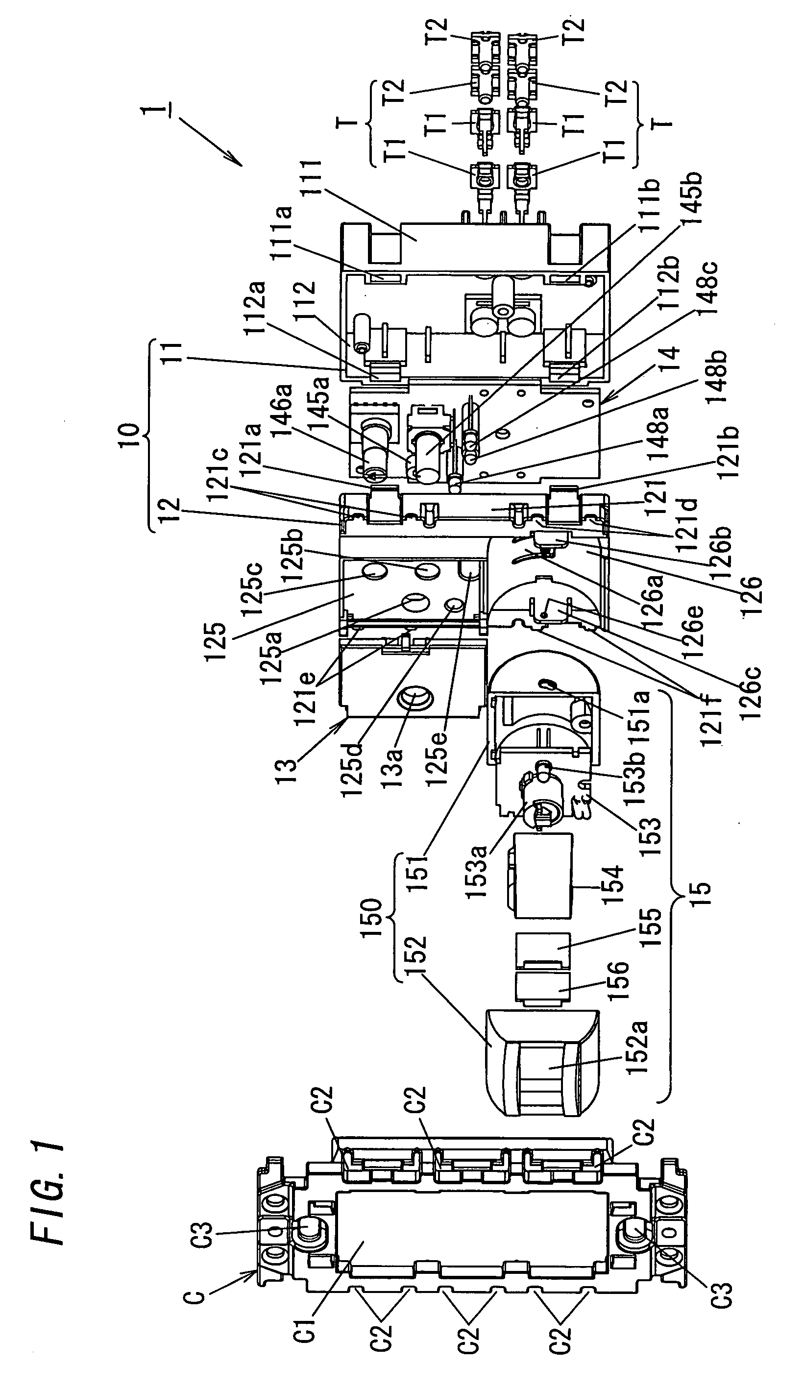
[0055]FIGS. 1 and 2 show a first embodiment according to the present invention, i.e., an infrared sensor switch 1. As shown in FIG. 2, the switch 1 is connected with a main control unit A and a corresponding load unit B through two-wire signal cable Ls. This system of FIG. 2 is usually provided with load units (B) and switches (1).

[0056]The unit A includes a communication circuit functioning as a transmitter and a receiver. Based on the time division multiplexing, the unit A sends out a transmission signal through the signal cable Ls, and sends and receives information to or from each unit B and each switch 1 through the transmission signal. As shown in FIG. 3, the transmission signal Vs is a time division multiplexing signal that is a bipolar signal of ±24V and includes start pulse ST, mode data MD, address data AD, control data CD, error correction code CS and signal return period WT. The start pulse ST represents the start of the signal Vs. The mode data MD is data representing a...

second embodiment

[0083]FIGS. 16A and 16B show a second embodiment according to the present invention, i.e., an infrared sensor switch 2. In addition to a housing 20 and a sensor block 25 which are configured in the same way as the first embodiment, the switch 2 comprises a main circuit block 24 further including a drive circuit 249. That is, the housing 20 comprises a case 21, a lid 22 and a cover 23, while the block 25 comprises a housing 250 (body 251 and cover 252), a sensor circuit block 253 (infrared sensor 153a, etc.), a lens 254 and shutters (not shown).

[0084]The circuit 249 is constructed with a servo motor 269a, a gear 269b and so on. The motor 269a is driven by the CPU of the block 24 in accordance with an instruction (e.g., up or down instruction) entered through a remote controller (not shown) and the wireless transmitting / receiving circuit of the address setting circuit in the block 24. The gear 249b is attached to the motor 269a and engages with slits (251c) of the body 251. In this co...

third embodiment

[0086]FIGS. 17A and 17B show a third embodiment according to the present invention, i.e., an infrared sensor switch 3. The switch 3 is constructed of a housing 30, a main circuit block 34 and a sensor block 35, and is characterized by the block 35 retained by the housing 30 so that the center axis of a detection range of an infrared sensor 153a in the block 35 can be rotated about a horizontal axis from forward to backward.

[0087]That is, in addition to a case 31 and a cover 33 which are configured in the same way as the first or the second embodiment, the housing 30 comprises a lid 32 that has retaining pieces 326b and 326c formed with toothed notches 326d and 326e, respectively, as shown in FIGS. 17A and 18 in stead of the elastic piece 126a and the protrusions (126e). The lower part of each retaining piece (notch) protrudes to prevent the block 35 from falling. On the other hand, the block 35 comprises a housing 350 of which each round end is formed with a tubular axis (rotation a...


PUM


Abstract

An infrared sensor switch of the invention comprises an infrared sensor with a detection range, and a controller that uses the sensor to try to detect whether or not a person exists in the detection range and controls on and off of a corresponding load unit based on each detection result obtained from the sensor. The switch further comprises a sensor block provided with the sensor, and a housing that is put in a wall and retains the block so that the center axis of the detection range can be rotated about a horizontal axis and rotated up to at least 40 degrees downward from a forward direction of 0 degree.

Description

TECHNICAL FIELD[0001]The invention relates generally to infrared sensor switches and more particularly to an infrared sensor switch that uses an infrared sensor to try to detect whether or not a person exists in a detection range of the sensor and controls on and off of a corresponding load unit based on the detection result.BACKGROUND ART[0002]This sort of infrared sensor switch is installed on, for example, a ceiling, a wall or the like to be utilized as an energy-saving unit. For example, a terminal unit described in Japanese Patent Application Publication No. H6-245282 issued Sep. 2, 1994 is installed on a wall. This unit comprises a printed circuit board on which an infrared sensor is mounted, and a rotating flame that retains the board and is rotated about a vertical axis through a direction adjusting knob. In case of this unit, the center axis of a detection range of the infrared sensor can be rotated about the vertical axis. However, since the positions of the top and bottom...

Claims


Application Information

Patent Timeline
Patent Type & Authority Applications(United States)
IPC IPC(8): G08B13/18
CPCG08B13/19Y02B20/44H05B37/0227H01H2239/07H05B47/13Y02B20/40H04Q9/00G08B13/189H04Q9/14
Inventor MATSUOKA, MAKIKOIEKI, TOMOHIROYOKOTA, KOJIYABU, HAJIMENAKANO, SUSUMUMIURA, KEI
Owner PANASONIC CORP
Why Eureka
Try Eureka