

U-cover camera phone
a camera phone and lens cover technology, applied in the field of u-shaped lens phone cover, can solve the problem of low image quality of vga camera
- Summary
- Abstract
- Description
- Claims
- Application Information
AI Technical Summary
Benefits of technology
Problems solved by technology
Method used
Image

Examples
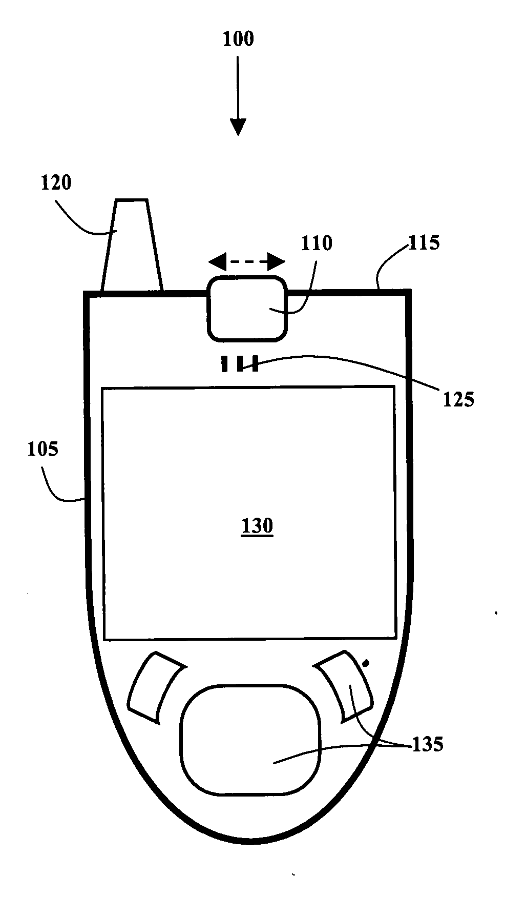
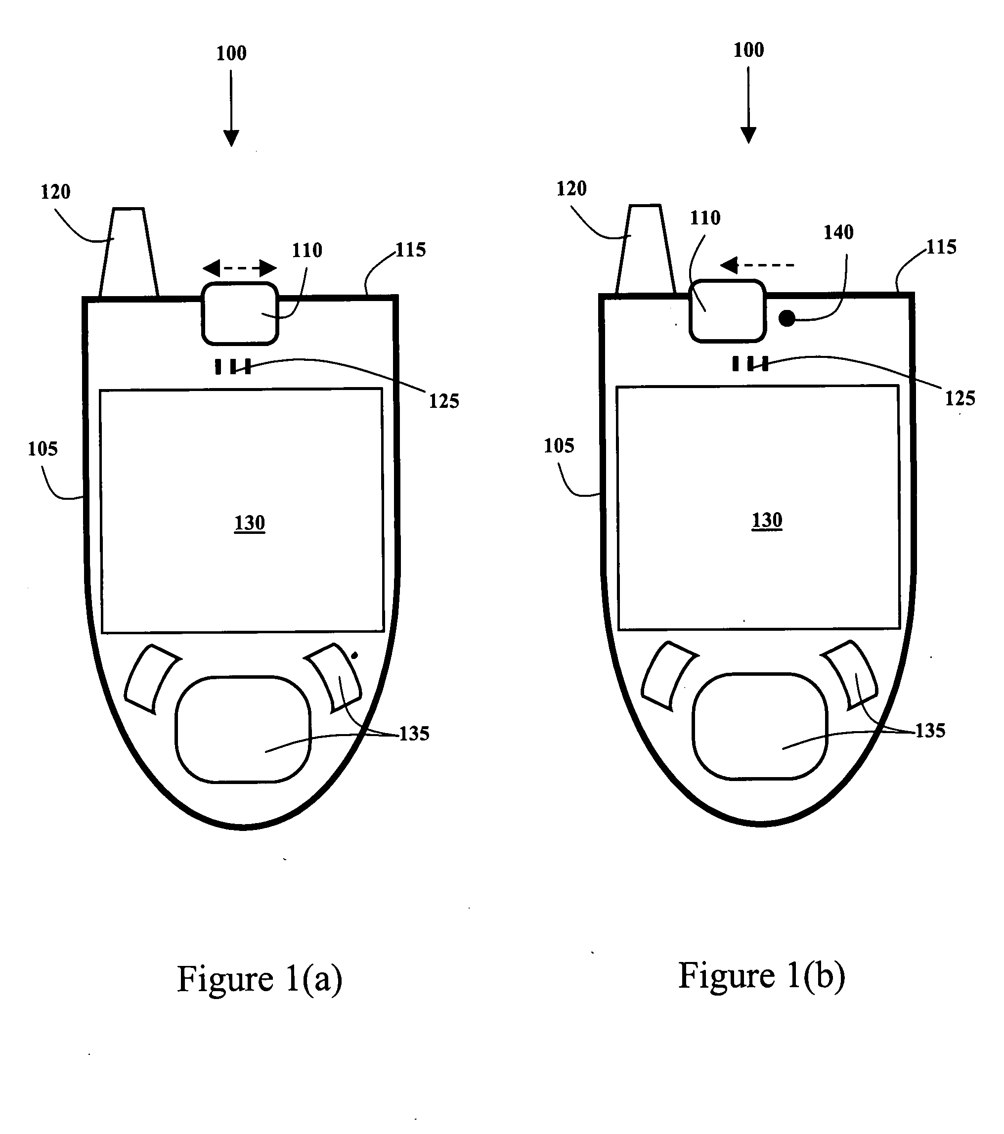
embodiment 100
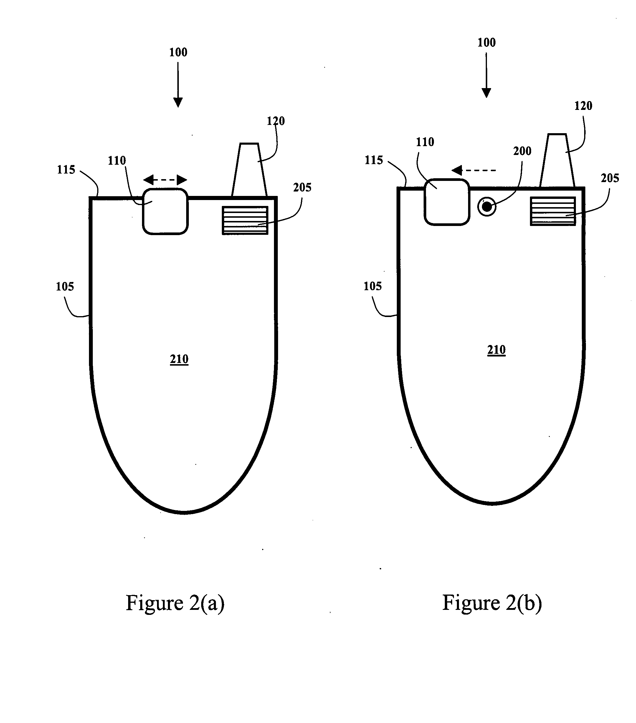
[0022]FIG. 2(a) shows the back 210 of the preferred embodiment 100 with the U-cover 110 in the first, or closed, position. The back 210 of the preferred smart phone includes a re-useable flash 205 that is permanently attached to the camera phone. The flash 205 is designed to work in conjunction with the second camera lens. The second camera lens is covered by the U-cover 110 when the cover 110 is in the first and second positions.
[0023]FIG. 2(b) shows the back 210 of the preferred embodiment 100 with the U-cover 110 in the third position, wherein the second digital camera lens 200, the “away camera”, is exposed. The second digital camera lens 200 is designed to operate with the same image capturing hardware in the camera phone as the first camera lens. Since, the second camera lens is capable of taking high-resolution pictures, the image capturing hardware preferably allows for the storage of more image information from the second camera. The second lens 200 faces away from the user...
embodiment 400
[0028]FIG. 4(b) shows the back 420 of the alternative embodiment 400 with the U-Cover 410 in the third position. When the U-Cover 410 is in the third position, the second, or away, camera lens 200 is exposed and may be used to take pictures and videos, depending on the desires of the user. The “away” lens 200 preferably includes zoom features, however other embodiments do not require a zoom feature. When the U-Cover 410 is in the second or third position, the cover slides into gaps in the device's body 405, just below the top 415 of the device. The U-Cover 410 of the alternative embodiment 400 is still an active, dual purpose, dual lens cover. When the electronic device 400 is powered OFF, the user can turn it ON simply by sliding the U-Cover 410 to the second or third position.
[0029]FIG. 5 shows steps in an exemplary method of operating the preferred embodiment. Initially, in step 500, the user is participating in a video telephone conference, wherein video information from the fac...
PUM
 Abstract
Description
Claims
Application Information