

Short Handle for a Long Stent
Patent Information
- Authority / Receiving Office
- US · United States
- Current Assignee / Owner
- MEDTRONIC VASCULAR INC
- Publication Date
- 2007-10-18
Smart Images
Figure 1 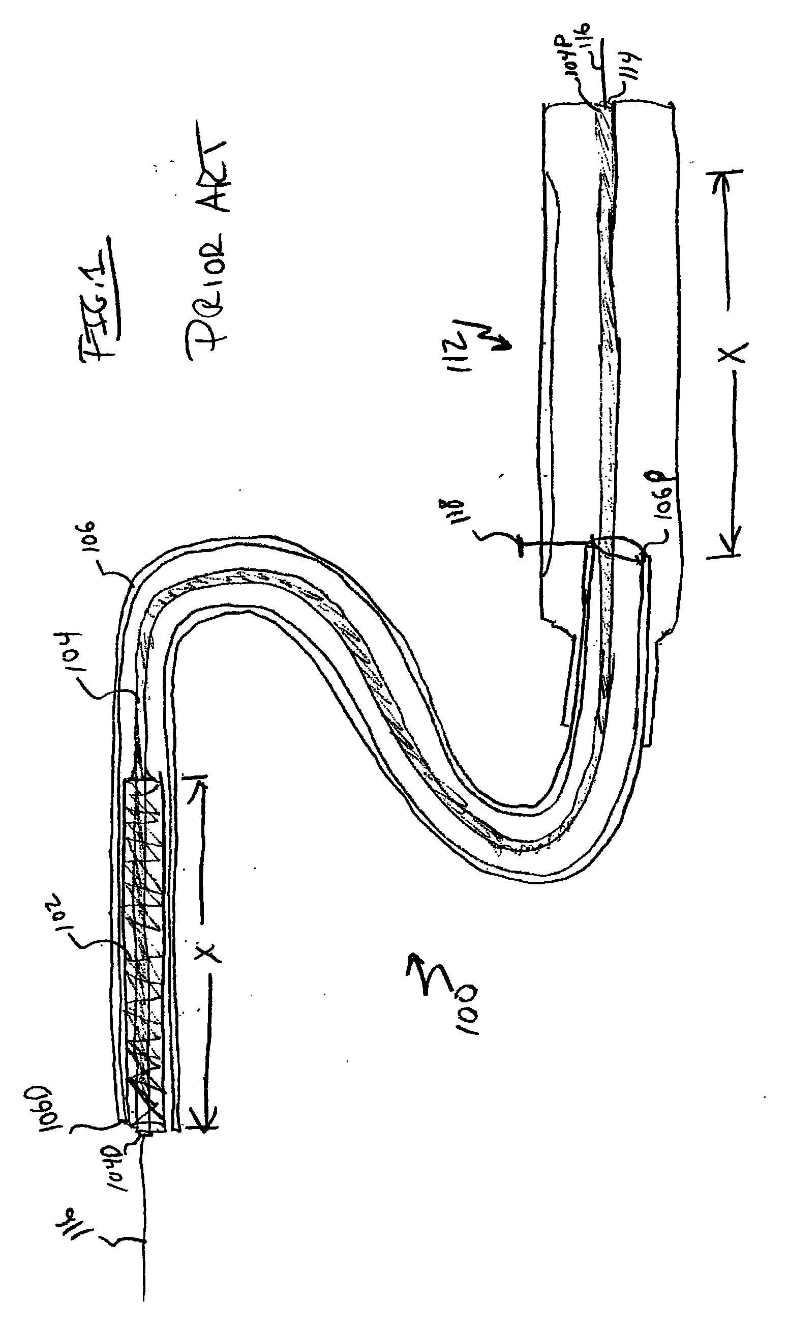
Figure 2 
Figure 3
Abstract
Description
BACKGROUND OF THE INVENTION
[0001] 1. Field of the Invention
[0002] The present invention relates to an intra-vascular device and method. More particularly, the present invention relates to a device for deployment of a stent for treatment of luminal, i.e., intra-vascular, diseases.
[0003] 2. Description of Related Art
[0004] In stent deployment systems, a self-expanding stent was restrained within a sheath. After positioning of the stent at the desired location via fluoroscopic guidance, the physician retracted the sheath to deploy the stent, i.e., to expose the stent and allow it to self-expand. To completely deploy the stent, the physician had to retract the sheath over the entire length of the stent, which was relatively cumbersome and typically required the use of both hands of the physician in the case of long self-expanding stents.
[0005] To illustrate, FIG. 1 is a partially cutaway delivery system 100 for deploying a stent 102 in accordance with the prior art. Stent 102 is a ...