Reconfigurable Low-Profile Pneumatic Edge-Clamp Systems and Methods

Inactive Publication Date: 2007-10-25
THE BOEING CO
View PDF12 Cites 20 Cited by
  • Summary
  • Abstract
  • Description
  • Claims
  • Application Information

AI Technical Summary

Benefits of technology

[0005] The present invention provides pneumatic edge-clamp systems and methods for securing a workpiece during a manufacturing operation. Embodiments of the present invention may advantageously provide a low-profile edge-clamping system that operates with a short displacement, conforms to the surface contour of the panel, provides quick actuation, and that is readily reconfigurable as needed.

Problems solved by technology

For example, in the process of friction stir welding, a sheet aluminum panel is clamped against an aluminum substructure, such as an I-beam, to allow a high speed rotating spindle to engage the panel, causing friction-induced elevated temperatures which fuse the panel and substructure together.
A problem may arise when the friction stir welded joint is located near the edge of the panel since there is no space on the outside edge of the joint for the typical metal frames which house the pneumatic inflatable bladders.

Method used


Image

  • Reconfigurable Low-Profile Pneumatic Edge-Clamp Systems and Methods
  • Reconfigurable Low-Profile Pneumatic Edge-Clamp Systems and Methods
  • Reconfigurable Low-Profile Pneumatic Edge-Clamp Systems and Methods

Examples


Embodiment Construction

[0015] The present invention relates to pneumatic edge-clamp systems and methods for securing a workpiece during a manufacturing operation. Many specific details of certain embodiments of the invention are set forth in the following description and in FIGS. 1 through 8 to provide a thorough understanding of such embodiments. One skilled in the art, however, will understand that the present invention may have additional embodiments, or that the present invention may be practiced without several of the details described in the following description.

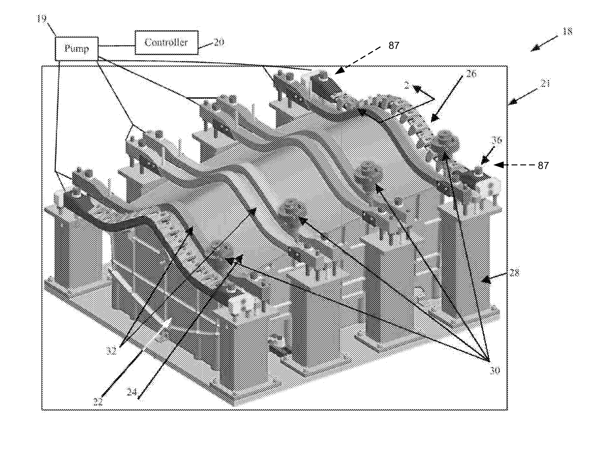
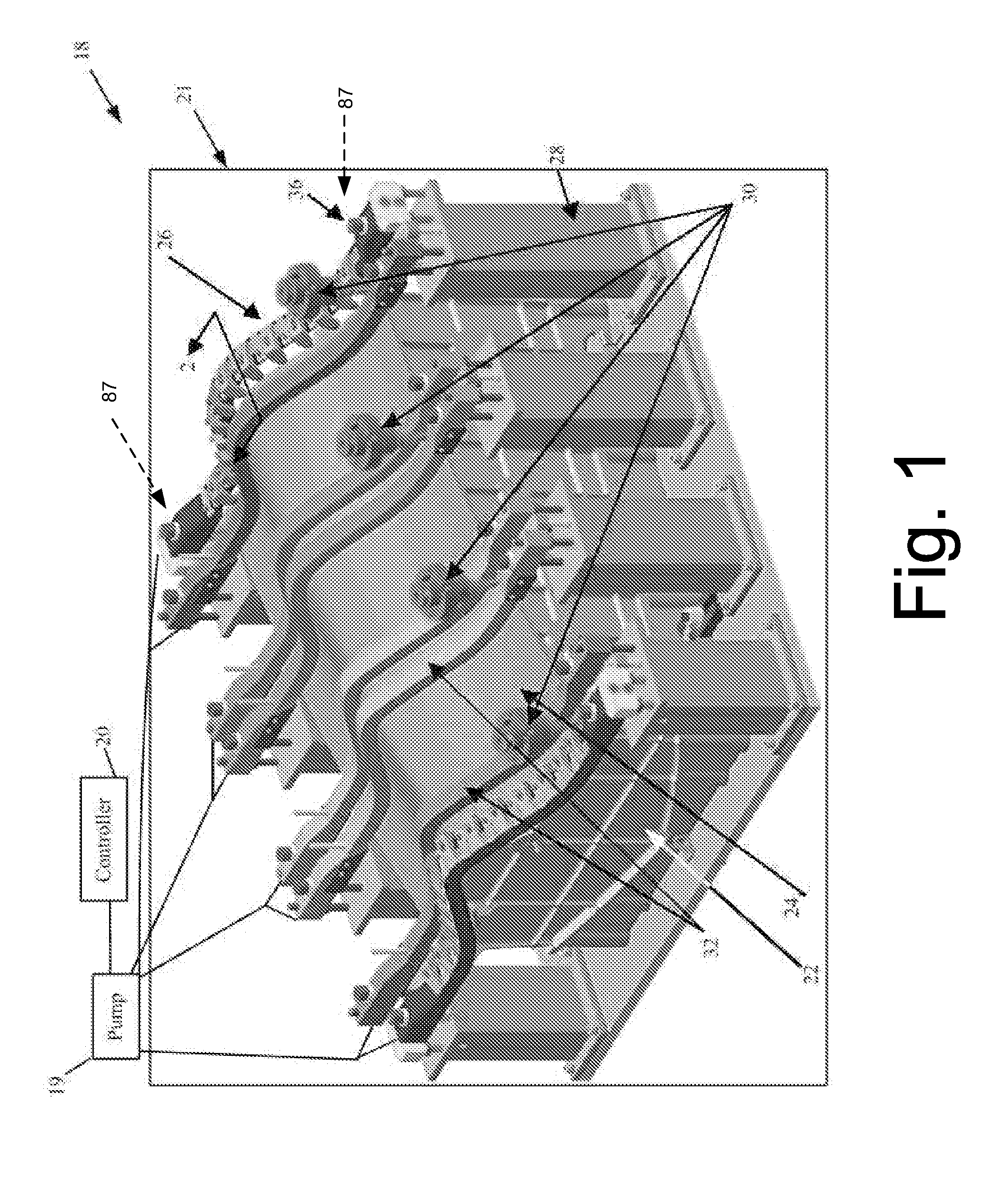
[0016]FIG. 1 illustrates a manufacturing system 18 in accordance with an embodiment of the present invention. In this embodiment, the manufacturing system 18 includes a controller 20, a pneumatic pump 19, and a clamping device 21. The controller 20 controls operation of the pneumatic pump 19 for supplying pressurized air to various components of the clamping device 21. The controller 20 may also control other components of the manufacturin...


PUM


Abstract

Pneumatic edge-clamp systems and methods are disclosed. In one embodiment, a clamping apparatus for applying a clamping force to a workpiece includes a beam member having a cavity disposed therein, and an inflatable member disposed within the cavity. The inflatable member is coupleable to a pressurization source. A clamping member is pivotably coupled to the beam member. The clamping member includes a first portion projecting at least partially over the cavity, and a second portion projecting laterally outwardly from the beam member over the workpiece. In operation, inflating the inflatable member applies a driving force to the first portion, rotating the clamping member, and applying a clamping force to the workpiece using the second portion.

Description

FIELD OF THE INVENTION [0001] This invention relates to systems and methods for securing a workpiece during a manufacturing operation, and more specifically, to pneumatic edge-clamp systems and methods that may be used, for example, in welding or other manufacturing operations. BACKGROUND OF THE INVENTION [0002] During many different types of manufacturing operations, it is necessary to secure the workpiece in position. For example, in the process of friction stir welding, a sheet aluminum panel is clamped against an aluminum substructure, such as an I-beam, to allow a high speed rotating spindle to engage the panel, causing friction-induced elevated temperatures which fuse the panel and substructure together. [0003] One proven method of clamping the aluminum panel is to use commercially available pneumatic inflatable bladders which expand against the panel to restrain movement of the panel and press it firmly against the substructure. Such inflatable flexible bladders are typically...

Claims


Application Information

Patent Timeline
IPC IPC(8): B23Q3/08
CPCB25B5/065B25B5/003
Inventor WOOD, JEFFREY H.MATLACK, MICHAEL P.WITTE, JAMES A.
Owner THE BOEING CO
Why Eureka
Try Eureka