Chain plate with wings

a technology of chain plate and abutment plate, which is applied in the field of chains, can solve the problems of large collision noise, and achieve the effect of reducing the collision between the chain plate and the abutment pla

Inactive Publication Date: 2007-10-25
KMC CHAIN INDUSTRIAL
View PDF3 Cites 18 Cited by
  • Summary
  • Abstract
  • Description
  • Claims
  • Application Information

AI Technical Summary

Benefits of technology

[0011]As such, the first wing can be spaced apart from the abutment plate by a shor...

Problems solved by technology

Excessively large spaces between the inner and outer chain plates 71, 72, however,...

Method used


Image

  • Chain plate with wings
  • Chain plate with wings
  • Chain plate with wings

Examples


Embodiment Construction

[0020]Before the present invention is described in greater detail in connection with the preferred embodiments, it should be noted that similar elements and structures are designated by like reference numerals throughout the entire disclosure.

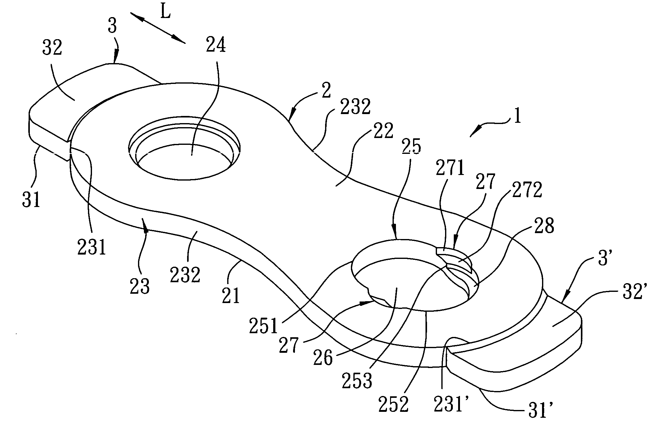
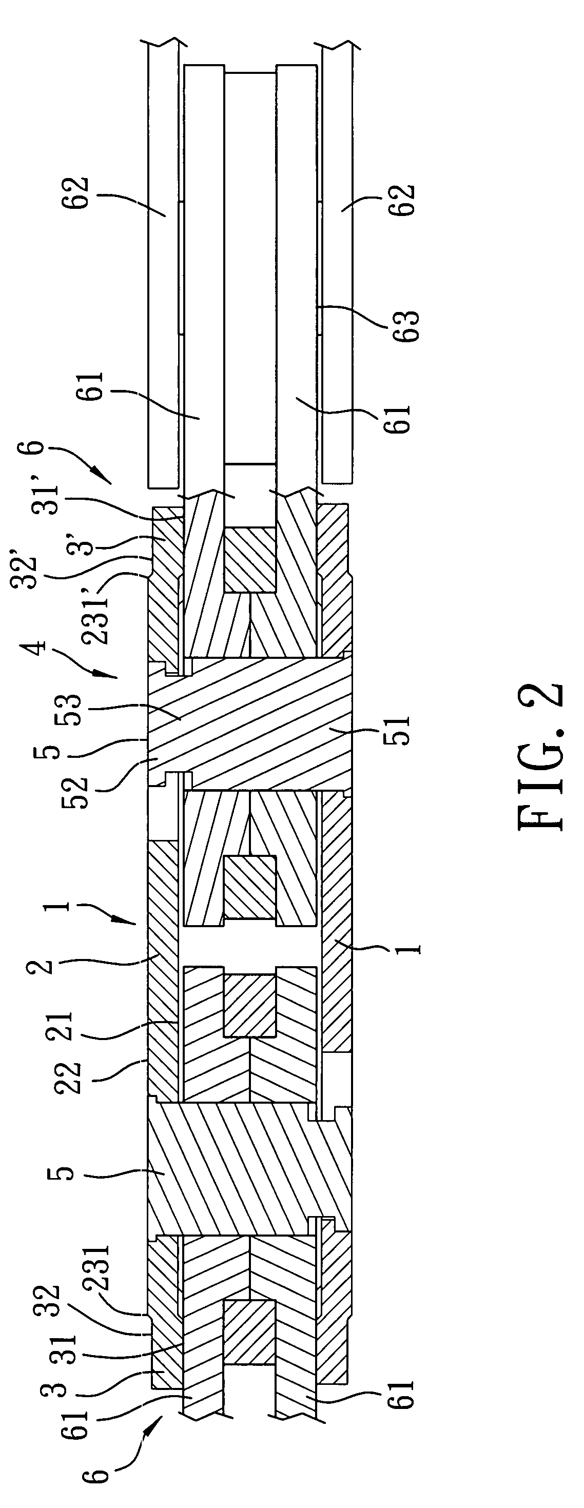
[0021]Referring to FIGS. 2 and 3, a chain typically includes a plurality of chain link units 6 and a connecting unit 4. Each of the chain link units 6 includes two inner chain plates 61, two outer chain plates 62 located respectively to two sides of an assembly of the inner chain plates 61, and a chain pin 63 extending through the inner and outer chain plates 61, 62. The connecting unit 4 includes two link pins 5 and two link plates interconnecting the link pins 5. The first preferred embodiment of a chain plate 1 according to this invention is applicable to any of the inner and outer chain plates 61, 62 and the link plates of the connecting unit 4, and is used with an abutment plate. When the chain plate 1 serves as any of the link plates of t...


PUM


Abstract

A chain plate includes a plate body and a first wing. The plate body has a first side surface adapted to face an abutment plate, a second side surface opposite to the first side surface, and an annular peripheral surface interconnecting outer peripheries of the first and second side surfaces and having first and second ends opposite to each other in a longitudinal direction. The first wing extends integrally from the first end of the peripheral surface in the longitudinal direction, and has a first side surface facing the abutment plate. The distance between the first side surface of the first wing and the abutment plate is smaller than that between the first side surface of the plate body and the abutment plate.

Description

CROSS-REFERENCE TO RELATED APPLICATION[0001]This application claims priority of Taiwanese Application No. 095114730, filed on Apr. 25, 2006.BACKGROUND OF THE INVENTION[0002]1. Field of the Invention[0003]This invention relates to a chain, and more particularly to a chain plate that is one element of a chain and that is formed with wings.[0004]2. Description of the Related Art[0005]Referring to FIG. 1, a conventional chain typically includes a plurality of chain link units 7 and a connecting unit 8. Each of the chain link units 7 includes two inner chain plates 71, a lining sleeve 70 interconnecting the inner chain plates 71, two outer chain plates 72 located respectively to two sides of an assembly of the inner chain plates 71, a chain roller 73 disposed between the inner chain plates 71, and a chain pin 74 extending through the lining sleeve 70 and connected to the outer chain plates 72. The connecting unit 8 includes two link pins 81 each extending through the inner chain plates 7...

Claims


Application Information

Patent Timeline
IPC IPC(8): F16G13/02
CPCF16G13/02F16G13/14F16G13/06
Inventor WU, DANIEL
Owner KMC CHAIN INDUSTRIAL
Why Eureka
Try Eureka