
Medical Instrument For Suction And Irrigation

a technology for medical instruments and irrigation, applied in the field of medical instruments for suction and irrigation, can solve the problems of difficult detection of visual information, inability to detect with other senses, and surgeons may have to look up from the operating site, etc., and achieve the effect of detecting elevations particularly easily

Inactive Publication Date: 2007-10-25
KARL STORZ GMBH & CO KG
View PDF14 Cites 46 Cited by
  • Summary
  • Abstract
  • Description
  • Claims
  • Application Information

AI Technical Summary

Benefits of technology

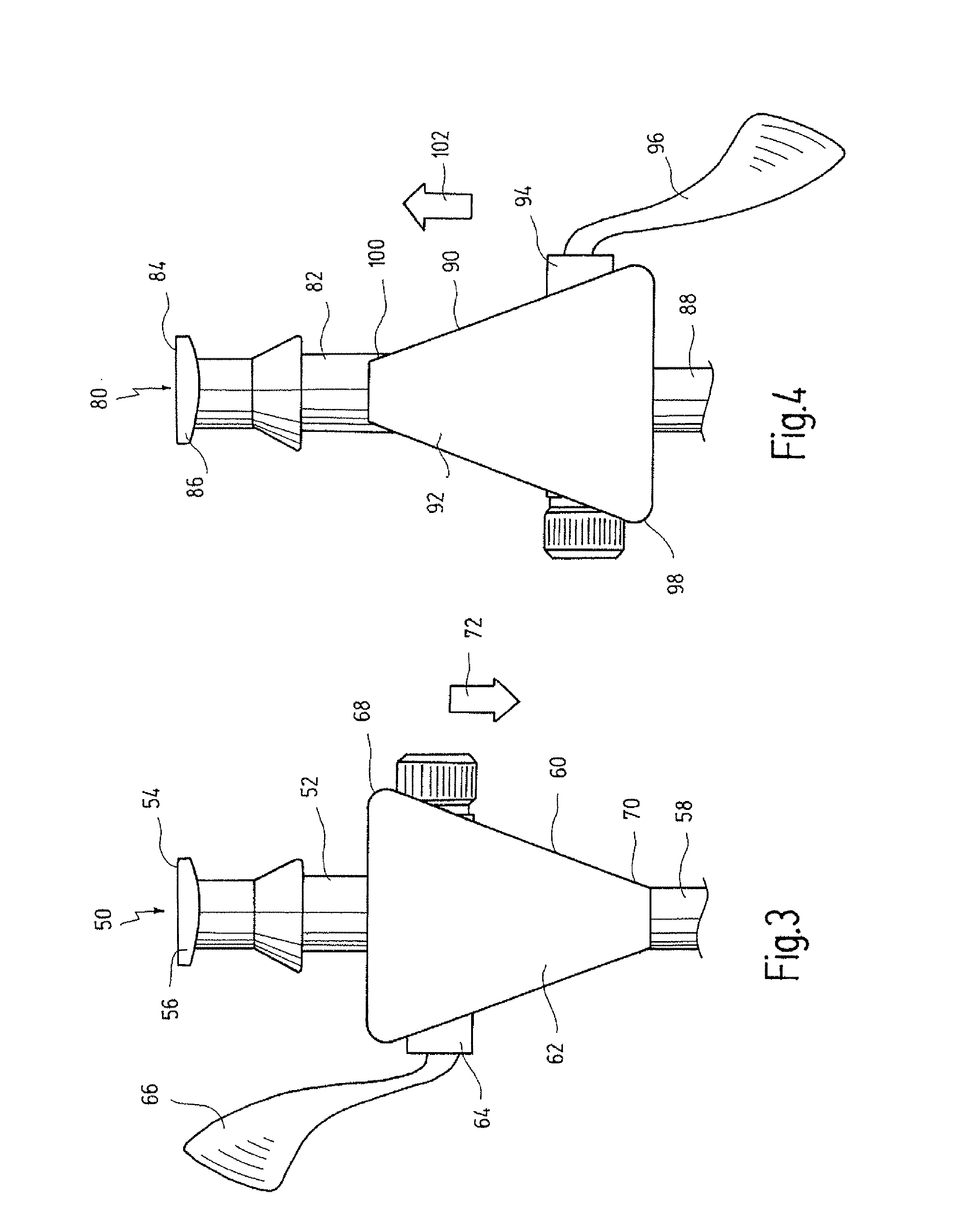
[0011] As a result of this measure, the directional indicator is located directly at the connector and thereby makes a quick detection of the direction of flow possible. If the body forms the tactile arrow-like portion, this also makes production easier, since the tactile arrow-like portion can be formed directly during the production of the body.
[0015] As a result of this measure, the directional information is directly accessible at the location at which the supply or removal of a fluid is initiated. During the process of taking hold of the valve in order to open or close it, the direction of flow of this valve is thereby detected almost automatically, which again contributes significantly to the safety of operating the instrument.
[0018] As a result of such an arrangement, a structure which tapers in the direction of flow and can be detected by touch is formed. In this embodiment the tactile arrow-like portion can be detected by touch particularly easily.
[0024] An engraving has the advantage that it can be provided on a connector in a structurally simple manner. It also has the advantage that even already existing instruments can in this way be provided with a tactile arrow-like portion according to the invention in a simple manner.
[0026] An elevation has the advantage that it can be formed during the forming of the connector in a simple manner in production engineering terms. This measure also has the advantage that elevations can be sensed by touch particularly easily.

Problems solved by technology

However, this has the disadvantage that the surgeon may have to look up from the operating site and cannot detect with other senses whether a connector and a valve possibly attached to it is an irrigation connector or a suction connector.
Furthermore, certain operations, in particular those in which fluorescence phenomena are used, are carried out in a dark operating theatre, which makes the detection of visual information much more difficult again.

Method used


Image

  • Medical Instrument For Suction And Irrigation
  • Medical Instrument For Suction And Irrigation
  • Medical Instrument For Suction And Irrigation

Examples


Embodiment Construction

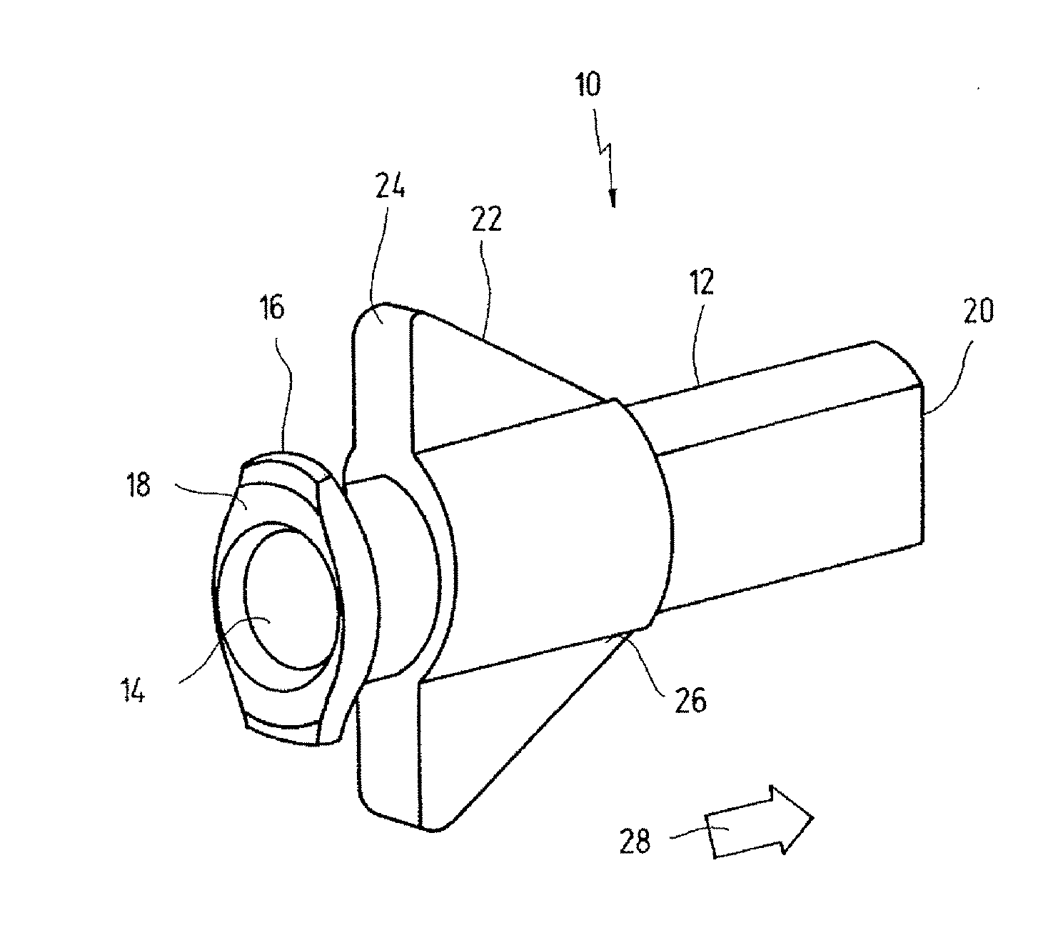
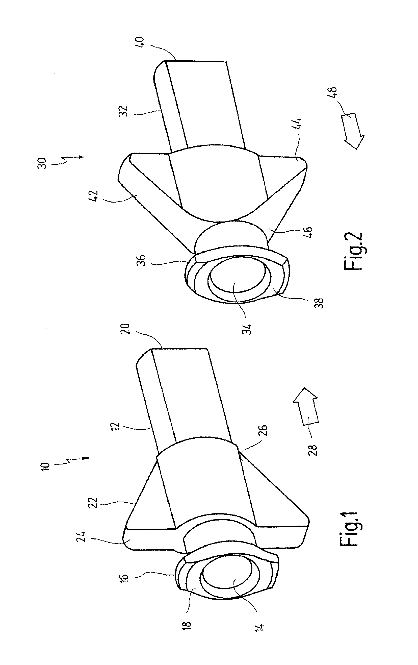
[0034] In FIG. 1, a connector is denoted in its entirety by the reference numeral 10.

[0035] The connector 10 comprises a body 12, through which a channel 14 runs. Via this channel 14, a fluid can be passed through the connector 10.

[0036] The body 12 comprises a first end 16, at which a connecting piece 18 is arranged. With this connecting piece 18, the connector 10 can be connected to a line for a fluid.

[0037] The body 12 further comprises a second end 20, at which the connector 10 can be connected to a medical instrument for suction and irrigation.

[0038] Arranged between the first end 16 and the second end 20 is a tactile arrow-like portion 22. This tactile arrow-like portion 22 comprises a first region 24 and a second region 26. The first region 24 has a greater width than the second region 26 in a plane along the direction of flow, i.e. along the channel 14. The tactile arrow-like portion 22 tapers continuously from the first region 24 to the second region 26. As a result, th...


PUM


Abstract

The invention relates to a medical instrument for suction and irrigation, comprising at least two connectors having a body comprising a channel for the passage of a fluid. The at least connectors comprise a tactile arrow-like portion that indicates a direction of flow of the fluid through the channel, whereby a tactile arrow-like portion of one of the at least two connectors indicates a direction of flow towards the medical instrument, and a tactile arrow-like portion of another one of the at least two connectors indicates a direction of flow away from the medical instrument.

Description

BACKGROUND OF THE INVENTION [0001] The invention relates to a medical instrument for suction and irrigation which comprises at least two connectors having a body comprising a channel for the passage of a fluid. [0002] Medical instruments for suction and irrigation are known and are sold for example by the applicant for use in laparoscopy. [0003] These instruments serve for example for the purpose of cleaning a viewing window of an endoscope of blood or other body fluids during an endoscopic examination or treatment, or of removing blood and body fluids from an operating site. [0004] It is thereby important that the connecting lines are always attached to the correct connectors, since otherwise for example body fluids get into the irrigation portion of an instrument for suction and irrigation that has to be kept sterile, and can possibly also contaminate the sterile irrigation fluid. [0005] Previously, visual information has been provided on such instruments in the form of arrows or ...

Claims


Application Information

Patent Timeline
Patent Type & Authority Applications(United States)
IPC IPC(8): A61M31/00
CPCA61B1/015A61B1/12A61M2205/583A61M39/10A61M2205/582A61M1/0064A61M1/774
Inventor VAN MANEN, AGNES MARIA
Owner KARL STORZ GMBH & CO KG
Learn More