Quick connect system for a bicycle rack assembly

a bicycle rack and quick connection technology, applied in the direction of fastening means, traveling carriers, travelling articles, etc., can solve the problems of inconvenient or prohibitive access to the engine compartment, trunk or tailgate, and the carrier cannot be removed or extended unattractively beyond,

Inactive Publication Date: 2007-11-01
MIDWEST BUS CORP
View PDF63 Cites 16 Cited by
  • Summary
  • Abstract
  • Description
  • Claims
  • Application Information

AI Technical Summary

Benefits of technology

[0004]The invention relates to a quick connection and release assembly for a bicycle rack onto a bumper system. The assembly includes a bracket mounted onto the bumper and the bicycle rack releasably connectable to the bracket with a quick connection. The bicycle rack is moveable relative to the bracket between a working position extending generally forward of the bumper system and a stowed position extending generally vertically upwardly from the bumper. The bracket has a rear planar wall having through apertures for receiving bolts to mount to the bumper system of the vehicle. The bracket further has a pair of side walls extending from distal ends of the rear planar wall and a latch plate extending from a center portion of the rear planar wall. The side walls have releasably mounting means for the bicycle rack.

Problems solved by technology

These hitch-type bicycle carriers do not allow for pivotal movement for placement of the bicycle carrier in either the stored position or the working position.
Therefore, when the bicycle carrier is not in use, then the carrier must either be removed or have it extend unattractively beyond the bumper
This semi-permanent mounting can make access to the engine compartment, trunk or tailgate inconvenient or prohibitive.

Method used


Image

  • Quick connect system for a bicycle rack assembly
  • Quick connect system for a bicycle rack assembly
  • Quick connect system for a bicycle rack assembly

Examples


Embodiment Construction

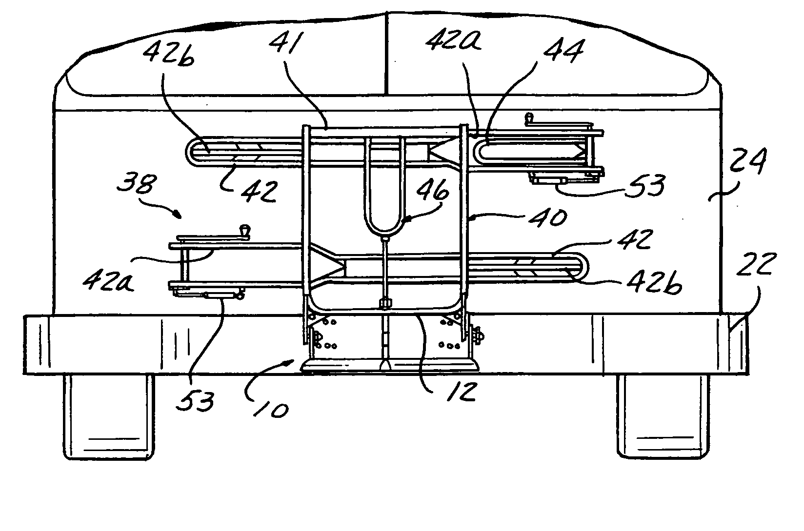
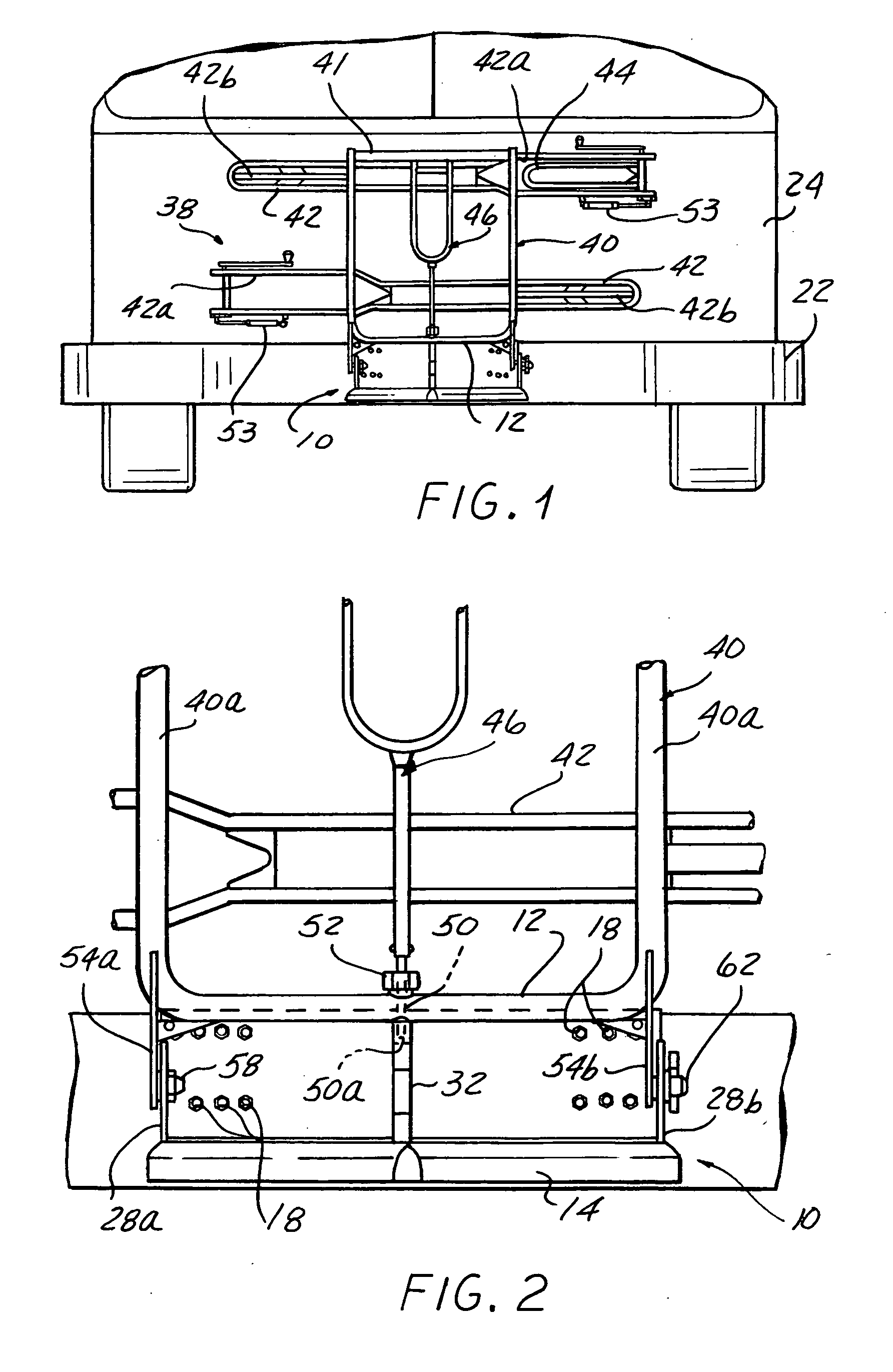
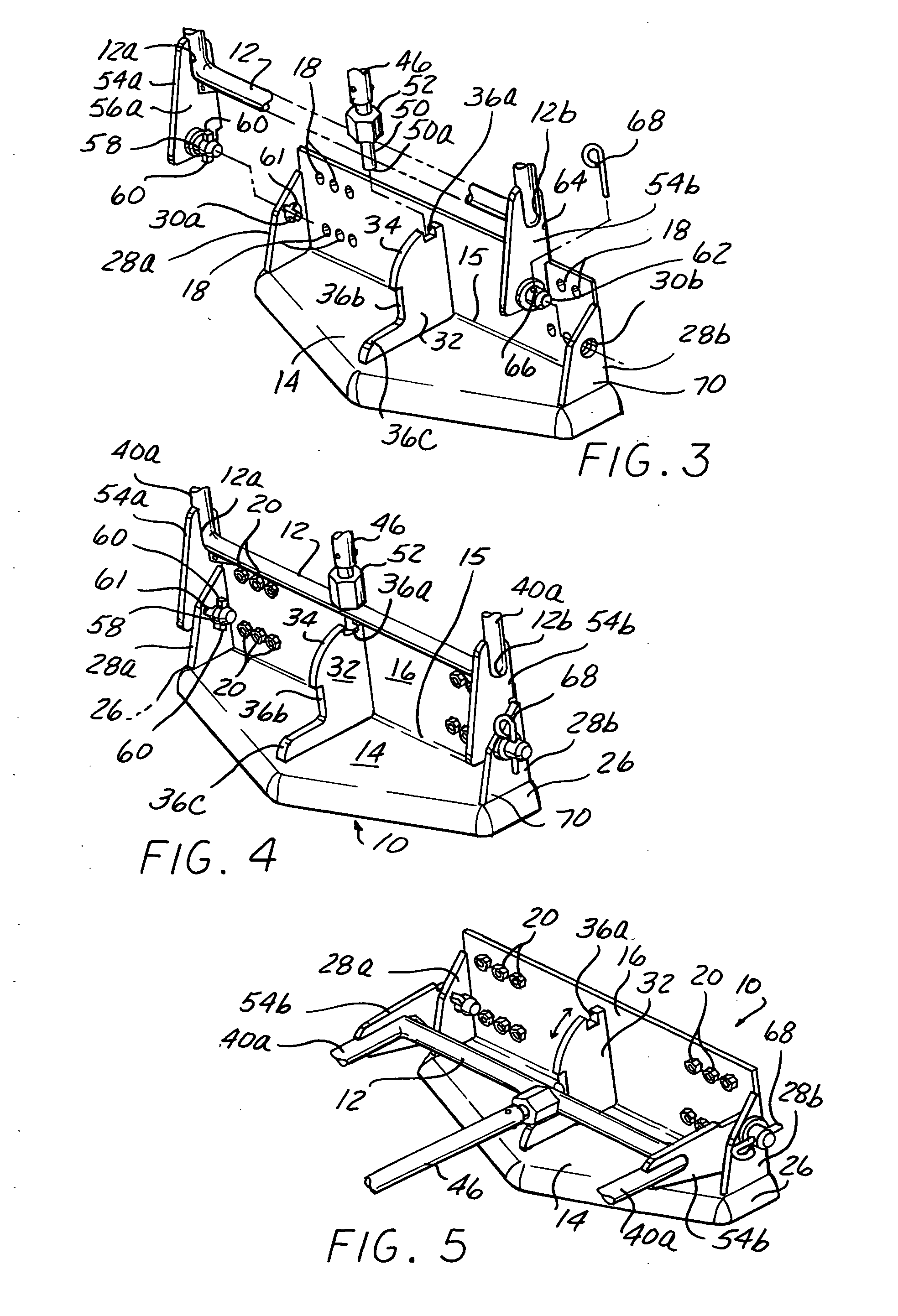
[0014]Referring to FIGS. 1-5, a quick connection and release assembly is provided for a bicycle rack onto a bumper system 22 of a vehicle 24 including two main components of a mounting bracket 10 and a pivoting arm 12. The mounting bracket 10 has a horizontal base member 14 and a rear vertical planar wall 16 attached along a rear lower edge 15 to the base member 14. The rear vertical wall has a plurality of aperture 18 therethrough for receiving bolts 20 for secure attachment to the vehicle bumper 22. Similar apertures (not shown) must be positioned in the bumper 22 for receiving the bolts 20.

[0015]The base member 14 may be made of a metal material. However, the base member 14 may also be formed or coated with a suitable rubberized material such as urethane or neopreen having similar attributes of the bumper 22, since the base member 14 extends beyond the bumper 22.

[0016]Extending from the rear planar walls along each lateral edge 26 of the base member 14 is a side wall 28a, 28b. Ea...


PUM


Abstract

A quick connect assembly for mounting a bicycle rack to a vehicle bumper includes a mounting bracket securely connectable to the bumper and a pivoting arm integrally connected to the bicycle rack and mountable to the mounting bracket. The mounting bracket has a horizontal base member and a vertical wall extending from the rear edge of the base member. Along each lateral edge of the base member is a vertical side wall having through apertures for receiving portions of the pivoting arm. A latch plate is centrally located on the mounting bracket between the two side walls. The latch plate has notches formed therein for receiving a latch pin of the pivoting arm to hold the bicycle rack in the vertically upward position or the horizontal working position. An arcuate cam formation separates the notches. The pivoting arm has spaced side plates each having a side extending peg for disposition in the apertures of the side walls. One peg has locking tabs and the other peg has a through aperture for receiving a cotter pin to secure the pivoting arm to the mounting bracket when the latch pin is in one of the notches.

Description

[0001]This application claims priority of provisional patent application Ser. No. 60 / 796,495 filed on May 1, 2006, herein incorporated in its entirety by reference.BACKGROUND OF THE INVENTION[0002]This invention relates to motor vehicle bicycle rack assembly. Vehicle bicycle carriers for connection to a vehicle exterior bumper are well known. A common type of bicycle carrier attaches to a vehicle's hitch for support thereon. These hitch-type bicycle carriers do not allow for pivotal movement for placement of the bicycle carrier in either the stored position or the working position. Therefore, when the bicycle carrier is not in use, then the carrier must either be removed or have it extend unattractively beyond the bumper[0003]Other types of bicycle carriers may include pivotal movement. However, these carriers are generally mounted on the vehicle bumper in a semi-permanent manner by bolts. This semi-permanent mounting can make access to the engine compartment, trunk or tailgate inco...

Claims


Application Information

Patent Timeline
Patent Type & Authority Applications(United States)
IPC IPC(8): B60R9/00B60R11/00
CPCB60R9/10Y10S224/924
Inventor GUNN, GEORGE
Owner MIDWEST BUS CORP
Why Eureka
Try Eureka