Inverter apparatus

a technology of inverter and display device, which is applied in the direction of electrical apparatus, instruments, light sources, etc., can solve the problems of mounting area, power consumption, cost, etc., and achieve the effect of simplifying the image display devi

Active Publication Date: 2007-11-01
ROHM CO LTD
View PDF10 Cites 13 Cited by
  • Summary
  • Abstract
  • Description
  • Claims
  • Application Information

AI Technical Summary

Benefits of technology

[0026] According to the embodiment, a plurality of the fluorescent lamps can be driven by a small control circuit, so that the image display apparatus can be simplified.

Problems solved by technology

In this case, if a plurality of the control circuits are incorporated in the liquid crystal television, there are disadvantages in terms of mounting area, cost, and power consumption.

Method used


Image

  • Inverter apparatus
  • Inverter apparatus
  • Inverter apparatus

Examples


first embodiment

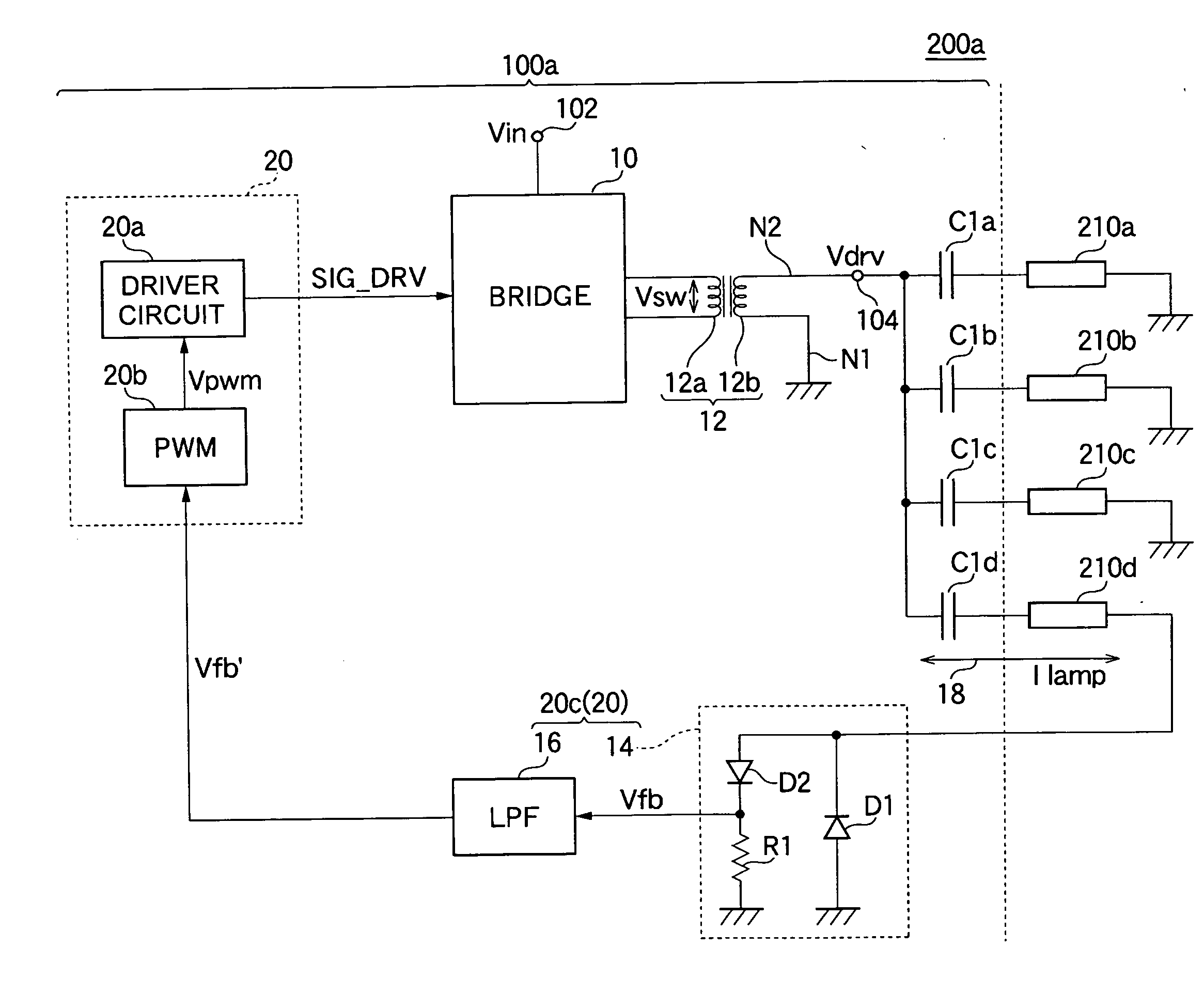
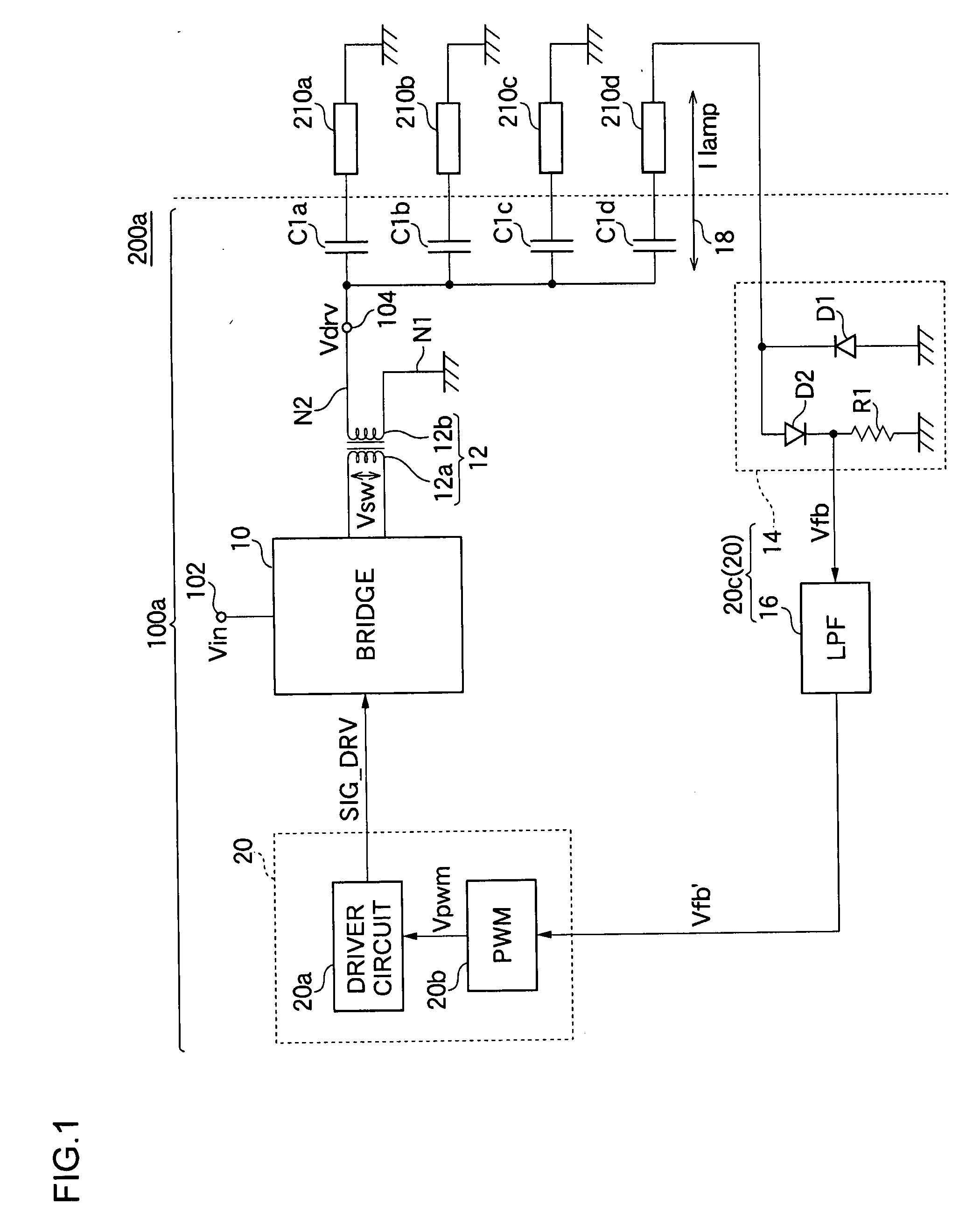
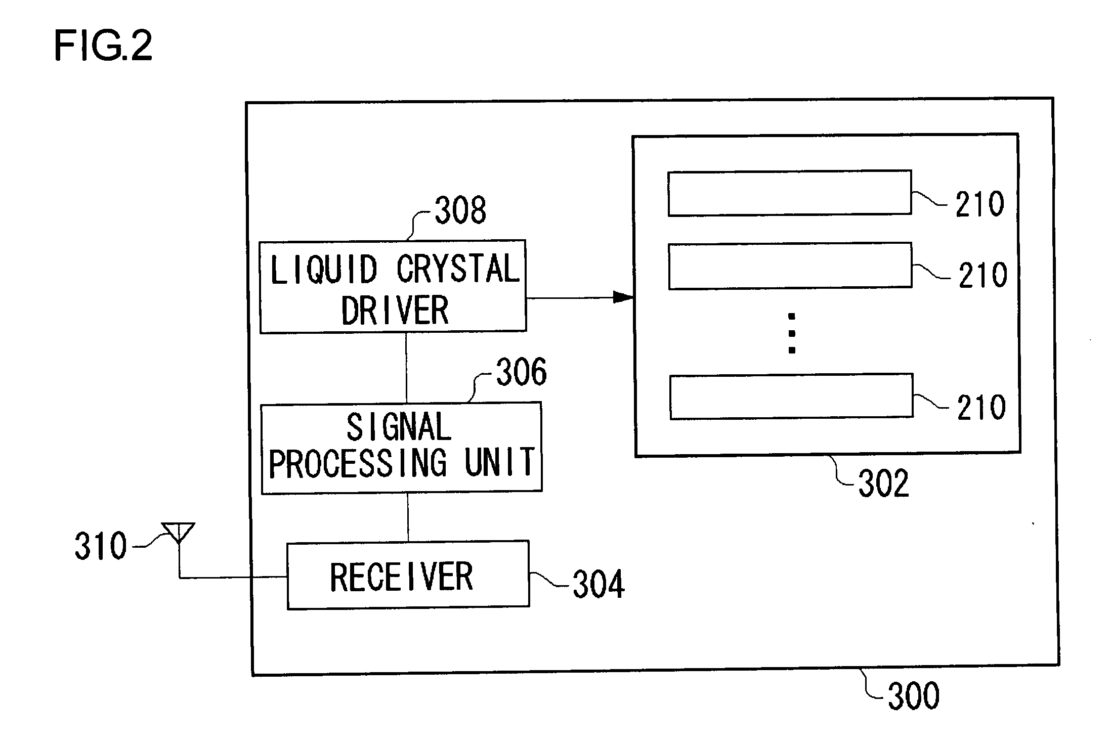
[0035]FIG. 1 is a circuit diagram illustrating a construction of a light emitting apparatus 200a according to a first embodiment of the present invention. FIG. 2 is a block diagram illustrating a construction of a liquid crystal television 300 provided with the light emitting apparatus 200a of FIG. 1. Referring to FIG. 2, the liquid crystal television 300 is connected to an antenna 310. The antenna 310 receives a broadcasting wave and outputs a received signal to a receiver 304. The receiver 304 detects and amplifies the received signal and outputs the resulting signal to a signal processing unit 306. The signal processing unit 306 outputs to a liquid crystal driver 308 an image data which can be obtained by demodulating a modulated data. The liquid crystal driver 308 outputs the image data to each scan line of a liquid crystal panel 302, so that an image can be displayed. As a backlight for the liquid crystal panel 302, a plurality of fluorescent lamps 210 are disposed on a rear su...

second embodiment

[0060]FIG. 3 is a circuit diagram illustrating a construction of a light emitting apparatus 200b according to a second embodiment. Now, the construction and operations of an inverter 100b are described in terms of difference to the inverter 100a according to the first embodiment.

[0061] The inverter 100b according to the embodiment is different from the inverter 100a according to the first embodiment in terms of a current path which is monitored by the control circuit 20. More specifically, in the inverter 100a according to the first embodiment, the current flowing through the current path including the predetermined load is monitored. However, in the inverter 100a according to the embodiment, the current flowing through a current path 19 including the secondary winding 12b of the transformer 12 is monitored.

[0062] In the inverter 100b shown in FIG. 3, the feedback circuit 20c is provided on the current path 19 including the secondary winding 12b of the transformer 12 to generate t...

third embodiment

[0065] An inverter 100c according to a third embodiment is an application of the inverter 100b according to the second embodiment. FIG. 4 is a circuit diagram illustrating a part of a construction of a light emitting apparatus 200c according to the third embodiment.

[0066] As shown in FIG. 4, the light emitting apparatus 200c include two inverters 100b. Each of the inverters 100b has the same construction as that of the inverter 100b according to the second embodiment shown in FIG. 3. The two inverters 100b, that is, inverters 100bR and 100bL are provided to both sides of the fluorescent lamps 210a to 210d. The inverters 100bR and 100bL drive the loads so that the currents flowing through the secondary windings of the transformers 12R and 12L are constant values. The driving voltage VdrvR of the inverter 100bR and the driving voltage VdrvL of the inverter 100bL are inverted AC voltages.

[0067] According to the embodiment, a plurality of the fluorescent lamps 210 can be driven by the...


PUM


Abstract

A switching circuit includes a plurality of transistors connected to a primary winding of the transformer and alternately applies an input voltage and a ground voltage to the primary winding according to turning-on and turning-off of each of the transistors. A plurality of capacitors are provided to the respective fluorescent lamps. One ends of the capacitors are commonly connected to a secondary winding of the transformer, and the other ends thereof are connected to the respective fluorescent lamps. A control circuit monitors a current flowing through a predetermined current path among current paths of the entire circuits including an inverter and the fluorescent lamps and performs feedback control of the turning-on and turning-off states of a plurality of the transistors of the switching circuit to adjust supply of switching power to the primary winding of the transformer so that the monitored current can be maintained in a predetermined condition.

Description

BACKGROUND OF THE INVENTION [0001] 1. Field of the Invention [0002] The present invention relates to an inverter apparatus for converting a DC input voltage to an AC voltage and supplying the AC voltage to a load, and more particularly to, an inverter apparatus for driving a plurality of loads. [0003] 2. Description of the Related Art [0004] Recently, as a substitute for CRT televisions, thin, wide screen liquid crystal televisions have been widely provided. As a backlight for the liquid crystal television, a plurality of cold cathode fluorescent lamps (hereinafter, referred to as CCFLs) or a plurality of external electrode fluorescent lamps (hereinafter, referred to as EEFLs) are disposed on a rear surface of a liquid crystal panel. [0005] An inverter (DC / AC converter) which boosts up a DC voltage of about 12V and outputs an AC voltage is used for driving the fluorescent lamp such as the CCFL and the EEFL. The inverter converts a current flowing through the fluorescent lamp to a vo...

Claims


Application Information

Patent Timeline
Patent Type & Authority Applications(United States)
IPC IPC(8): H05B41/36
CPCH05B41/2827G02F1/1335H05B41/24
Inventor FUKUMOTO, KENICHINAM, GOANG-WOO
Owner ROHM CO LTD
Why Eureka
Try Eureka