[0010] The present invention provides a
system and method for improving inspection of lateral pipes by enabling the imaging head to focus on a target at longer range down a pipe than previously possible. In this regard, Applicants recognize that the performance of the inspection
system can be improved dramatically if the imaging head is positioned reliably in an optimum location with respect to the lateral pipe. This position is referred to herein as the “
sweet spot.” Generally, the optimum position is where the illumination source or lamp is positioned such that its light beam propagates down the pipe to the furthest extent possible before reflecting off the pipe wall and diffusing. Since a target must be well illuminated for effective imaging, the further light is able to propagate down the pipe, the greater the imaging range will be. If the pipe is essentially free of material, the
sweet spot will be approximately in the center of the pipe. If, however, the pipe is partially filled with material, particularly liquids which tend to reflect light, then the sweet spot will be approximately in the center point of the space above the material.
[0012] Second, the
system should be adjustable in situ. Applicants appreciate that often the user does not know the state or condition of the pipe prior to inspection (i.e., whether it contains material / debris). Therefore, to position the imaging head in the sweet spot, some degree of adjustability is required. The imaging head is preferably adjustable in situ to eliminate the need to withdraw the imaging head from the pipe for each adjustment.
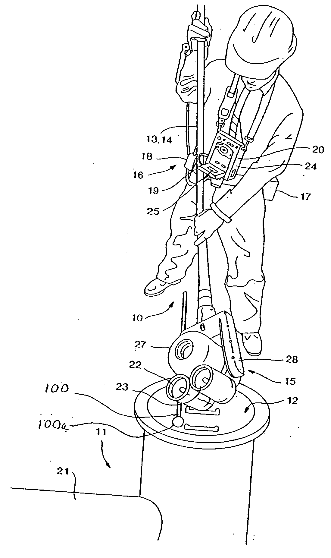
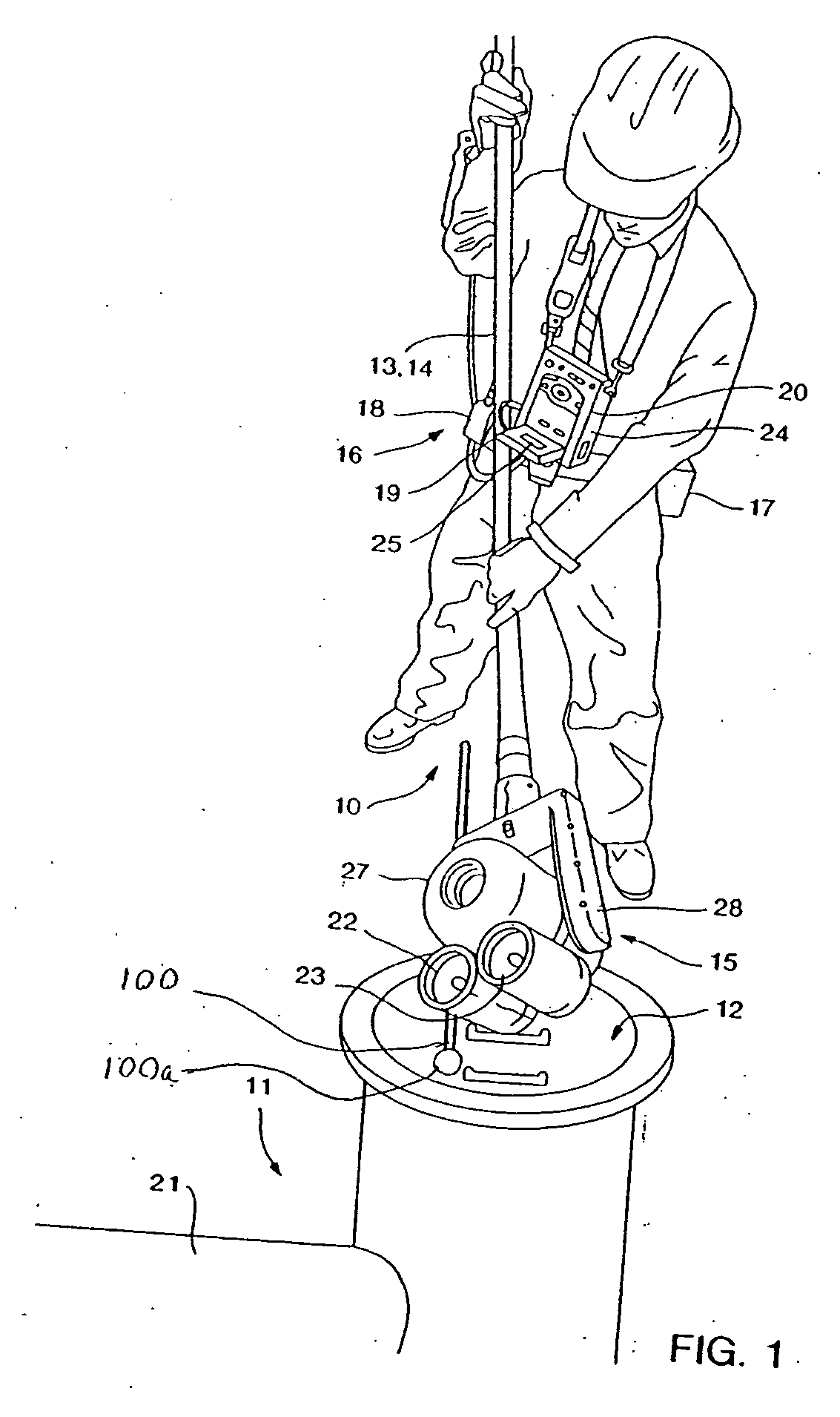
[0014] The imaging head of the present invention satisfies these opposing design objectives by employing a targeting fixture to provide moderate resilient force as a user urges the imaging head into the sweet spot. The targeting fixture comprises preferably a resilient member extending from the imaging head. In use, the inspection device is lowered into a manhole (or similar structure) until the targeting fixture rests on the bottom of a pipe (or similar structure). The user then pushes down on the imaging device until the imaging head is in the sweet spot. It has been found that pushing against the resilient targeting fixture provides a high degree of stability—essential during
high magnification. Thus, the targeting fixture of the present invention enables the imaging head to be positioned in the sweet spot to achieve maximum illumination down the pipe, while providing enhanced stability for focusing on targets further down the pipe than previously possible.
[0015] Aside from enhanced imaging range, Applicants have discovered a number of unexpected benefits and synergies of operating in the sweet spot. For example, operating in the sweet spot promotes the use of a lamp having narrow spot beams since they can be effectively aimed for maximum propagation. Previously, narrow spot beams were ineffective since they would reflect off the wall of the pipe and diffuse before their long range benefits could be realized. Therefore, operating in the sweet spot enables a
high intensity beam to reach a long-range target to facilitate imaging. Once the target is properly illuminated, the image can be focused. To this end, the present invention also provides for a convenient focusing device which allows the target to be magnified and manually focused with ease. Obtaining a clear image of the target in turn allows data such as target dimensions and range to be determined. More specifically, any long range distance or
size measurement depends on a well lit and steady image—accuracy of the survey depends upon it. Today the range of the range finder is far greater than the range of the camera and lighting. Accordingly, the combination of a range with a system having enhanced illumination and imaging is particularly synergistic.
[0016] In sum, the present invention involves recognizing the sweet spot in pipe inspection, identifying design objectives for operating in the sweet spot, providing a solution meeting the design objectives, and synergistically combining other technologies with the solution to provide an inspection system offering enhanced imaging of and data gathering from a target in a pipe at a range longer than conventional inspection devices can provide.
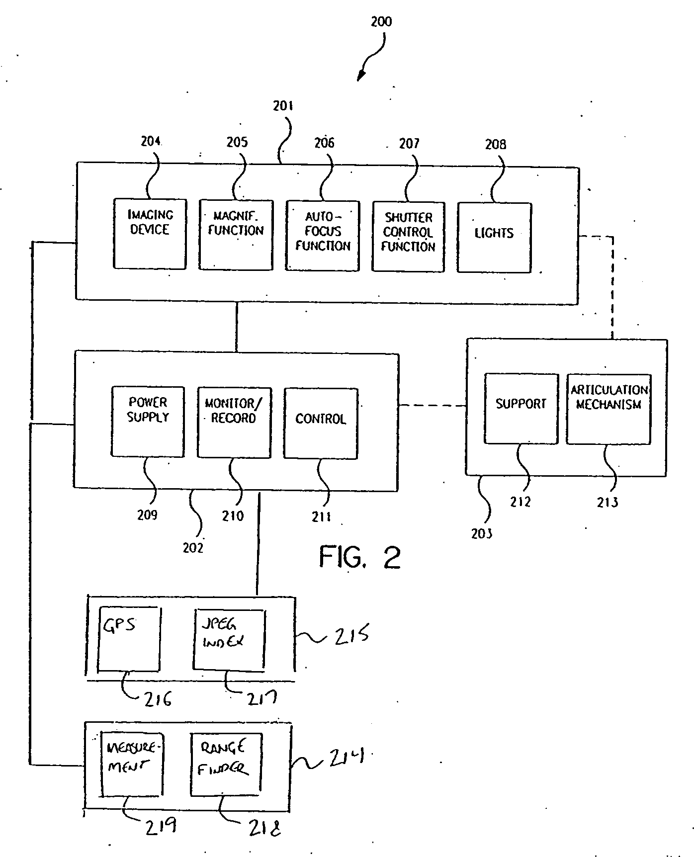
[0018] Another aspect of the invention is an inspection system for positioning the lights and imaging device in the sweet spot for enhanced long-range imaging down the pipe. In a preferred embodiment, the system comprises: (a) an imaging head comprising an imaging device adapted to convert an image to an
image signal, a lens optically coupled to the imaging device, and at least one lamp suitable for projecting a light beam; (b) a
support system electronically connected to the imaging device for receiving the
image signal from the imaging device and for transmitting a
zoom signal to the lens to achieve the desired
magnification; and (c) a
positioning system comprising an elongated member and a targeting fixture, the upon which the imaging head is attached and adapted for handling to position the imaging head in a desired position to view the elongated structure, and a targeting fixture extending outwardly from the imaging head, the targeting fixture having a distal end being biased outwardly from the imaging head such that, when pushed against a rigid surface, the distal end moves resiliently inward thereby effectively adjusting the position of the lamp relative to the rigid surface.

