Electrical connector having contact plates

a technology of contact plate and electric connector, which is applied in the direction of coupling device connection, coupling device two-part connection, coupling/disengagement of coupling parts, etc., can solve the problems of signal noise, interference with the purity of the signal being transmitted, and crosstalk become a significant problem

Active Publication Date: 2007-11-01
COMMSCOPE TECH LLC
View PDF12 Cites 100 Cited by
  • Summary
  • Abstract
  • Description
  • Claims
  • Application Information

AI Technical Summary

Problems solved by technology

Due to increases in data transmission rates in telecommunications systems, crosstalk has become a significant p

Method used


Image

  • Electrical connector having contact plates
  • Electrical connector having contact plates
  • Electrical connector having contact plates

Examples


Embodiment Construction

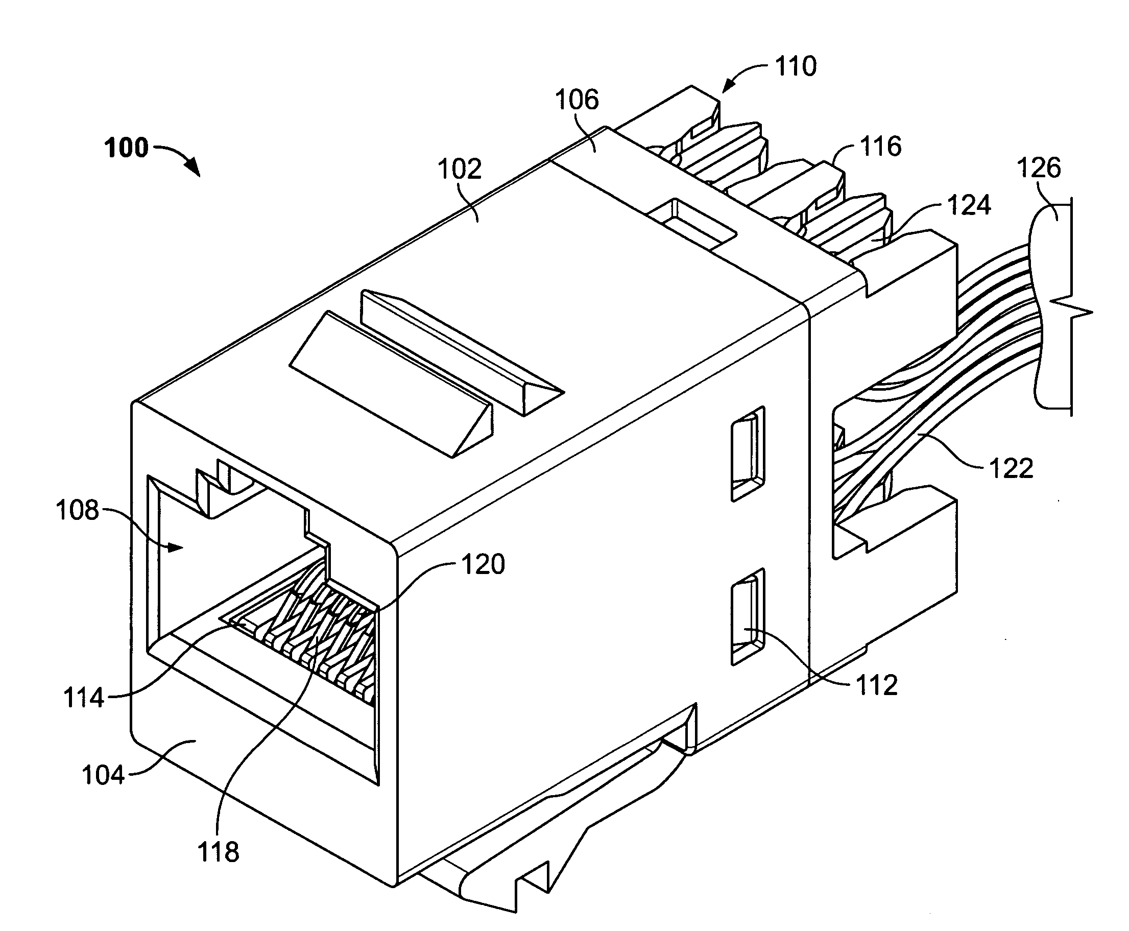
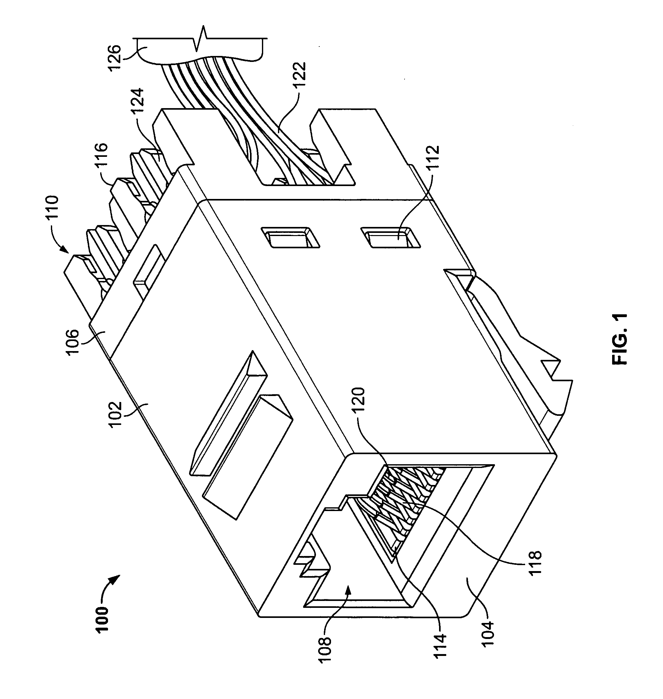
[0014]FIG. 1 illustrates a front perspective view of an exemplary electrical connector 100. In the illustrated embodiment, the connector 100 is a modular 8-pin connector, such as an RJ-45 outlet or jack. The connector 100 is configured for joining with a mating plug (not shown).

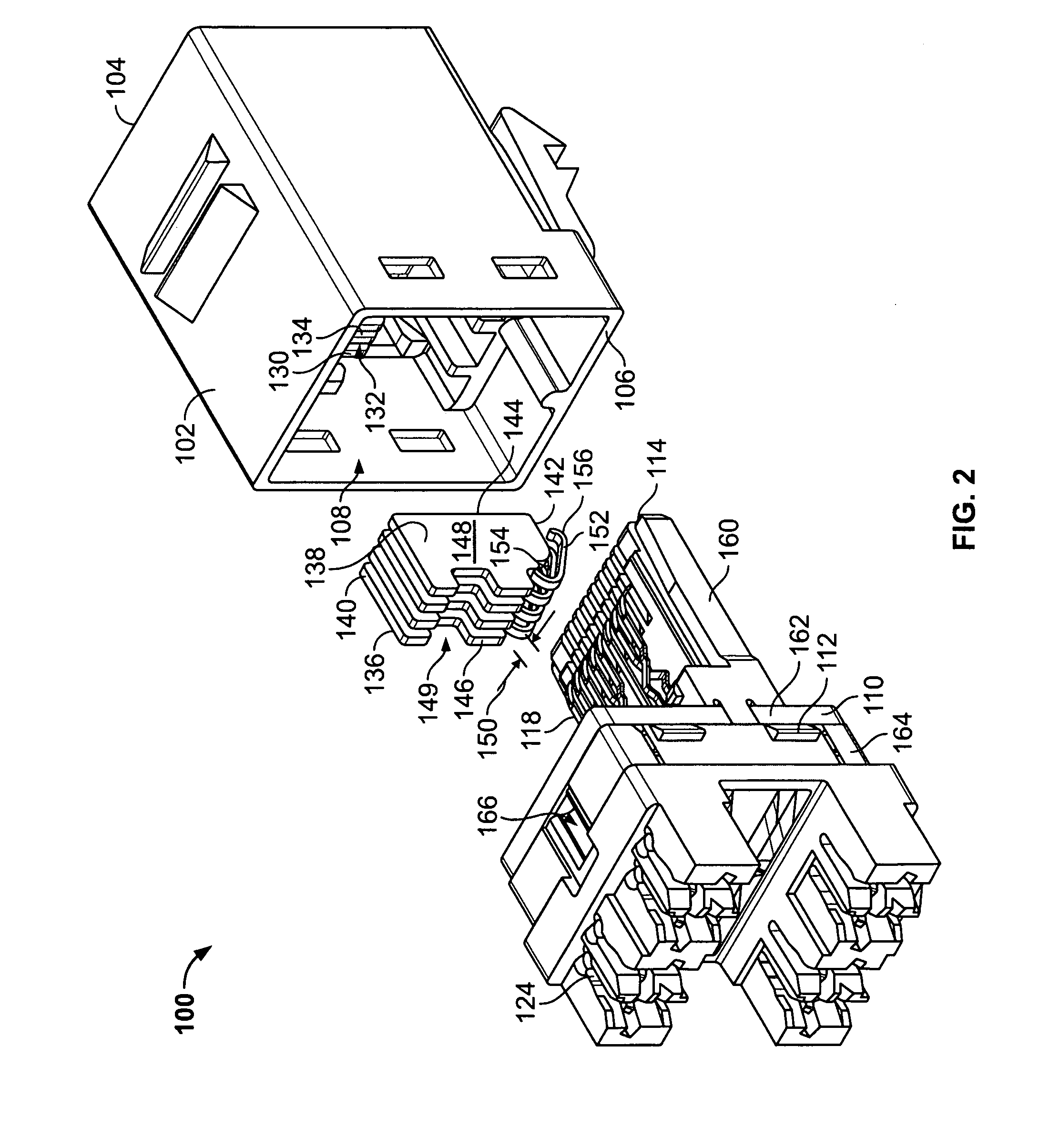
[0015] The connector 100 includes a housing 102 extending between a mating end 104 and a loading end 106. A cavity 108 extends between the mating end 104 and the loading end 106. The cavity 108 receives the mating plug through the mating end 104.

[0016] The connector 100 includes a contact sub-assembly 110 received within the housing 102 through the loading end 106 of the housing 102. The contact sub-assembly 110 is secured to the housing 102 via tabs 112. The contact sub-assembly 110 extends between a mating end 114 and a wire terminating end 116 and is held within the housing 102 such that the mating end 114 of the contact sub-assembly 110 is positioned proximate the mating end 104 of the housing 102. The ...


PUM


Abstract

An electrical connector includes a dielectric housing having a cavity configured to receive a mating connector therein and a contact subassembly having an array of contacts. Each of the contacts define a mating interface configured to engage the mating connector, and each of the contacts have a beam portion extending downstream of the mating interface to a contact terminating end. Contact plates are arranged within the cavity, such that each of the contact plates engage a corresponding one of the contacts at the beam portion of the contacts.

Description

BACKGROUND OF THE INVENTION [0001] This invention relates generally to electrical connectors, and more specifically, to electrical connectors having contact plates. [0002] Due to increases in data transmission rates in telecommunications systems, crosstalk has become a significant problem. Crosstalk may be defined as energy which is coupled from one signal line onto a nearby signal line by either capacitive or inductive coupling. This crosstalk results in signal noise which interferes with the purity of the signal being transmitted. [0003] A commonly used telecommunications wiring system is twisted pair wiring wherein pairs of wires are twisted about each other. The wires in a twisted pair carry differential signals and are thus known as signal pairs. Each of the wires in a signal pair carries an equal but opposite signal; that is, the wires carry signals of the same magnitude which are respectively positive and negative. Since these signals are equal but opposite, they generate fie...

Claims


Application Information

Patent Timeline
IPC IPC(8): H01R24/00H01R13/6464H01R24/58
CPCH01R13/6464Y10S439/941H01R24/64H01R13/6467H01R13/62H01R13/46H01R24/58
Inventor PEPE, PAUL JOHNBERT, LINDA ELLENSIGMON, NED
Owner COMMSCOPE TECH LLC
Why Eureka
Try Eureka