Rotary handle for controlled sequential deployment device

a technology of sequential deployment and control handle, which is applied in the field of controlled sequential deployment device, can solve the problem that interrelated components can provide significant load

a technology of sequential deployment and control handle, which is applied in the field of controlled sequential deployment device, can solve the problem that interrelated components can provide significant load

US20070255390A1Active Publication Date: 2007-11-01COOK MEDICAL TECH LLC +1

Image

  • Rotary handle for controlled sequential deployment device
  • Rotary handle for controlled sequential deployment device
  • Rotary handle for controlled sequential deployment device

Examples


Embodiment Construction

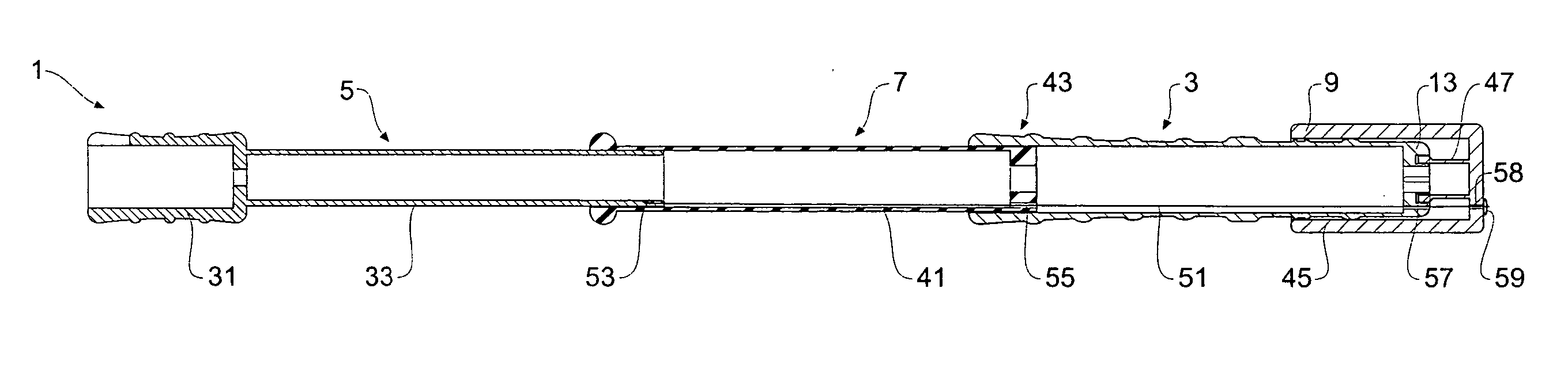
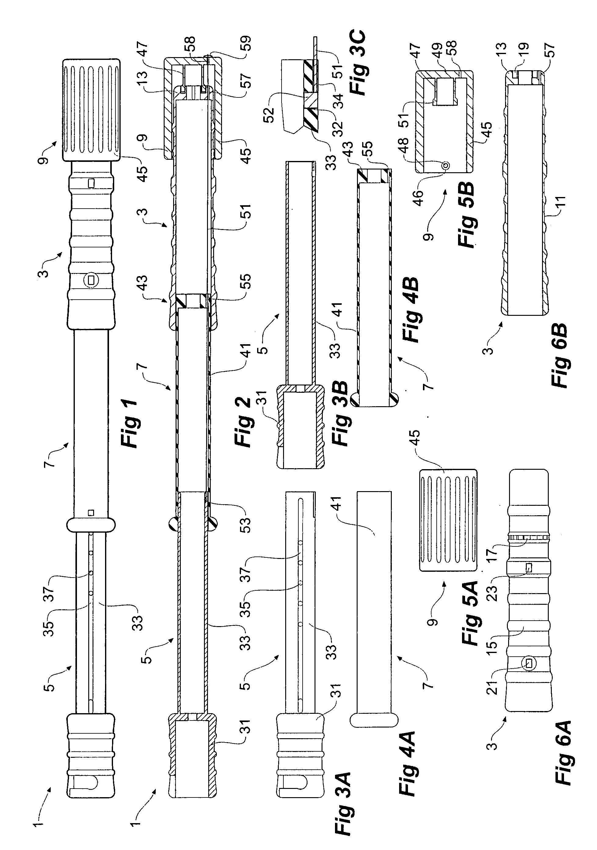
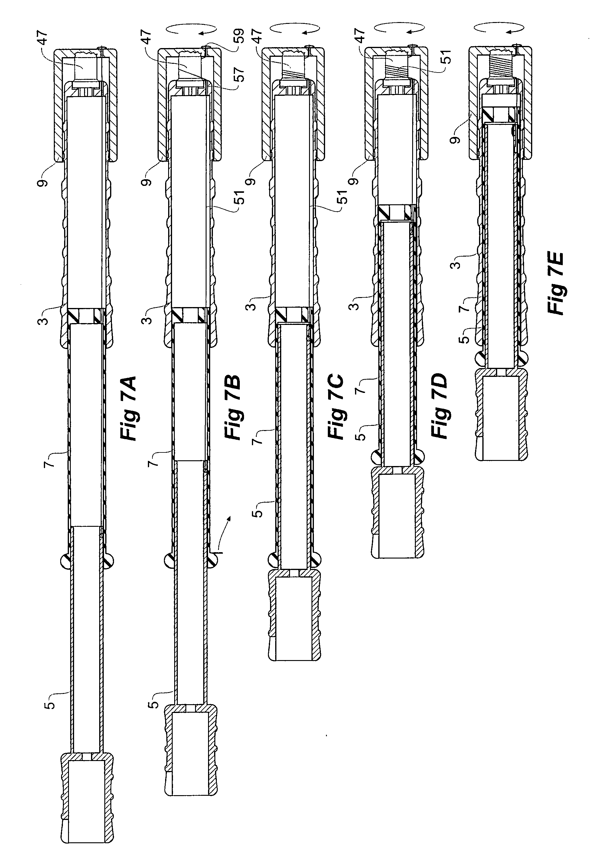
[0037] Now looking more closely at the drawings and in particular FIGS. 1 to 6 it will be seen that the stent graft introducer actuation assembly 1 comprises generally a fixed handle 3, a first slide or sliding handle 5 and a second slide or release portion 7. On the fixed handle 3 is a rotary handle 9.

[0038] The fixed handle 3 as shown in details in FIGS. 6A and 6B comprises an elongate tubular body 11 with a closed distal end 13. Hand grips 15 are provided on the outside of the fixed handle 3.

[0039] A toothed ring 17 is moulded into the outer surface of the fixed handle 3, the use of which will be discussed later. An annular groove 19 in the distal closed end 13 acts as a support for a winch drum which is integral with the rotary handle 9 as will be discussed later. An aperture 21 is provided for a removable second stop pin and aperture 23 is for a third removable stop pin as will be discussed later.

[0040] First slide 5 as shown on detail in FIGS. 3A and 3B includes a socket 31...


PUM


Abstract

A stent graft introducer actuation assembly (1) having a fixed handle (3) and at least one sliding handle (5, 7), the sliding handle or handles telescoping within the fixed handle, and a winch arrangement (9) to retract the sliding handle into the fixed handle. There may be provided arrangements to give a mechanical advantage to the winch arrangement.

Description

CROSS-REFERENCE TO RELATED APPLICATIONS [0001] This application is related to and claims priority from U.S. Provisional Patent Application No. 60 / 795,634 filed Apr. 26, 2006 entitled “Rotary Handle for Controlled Sequential Deployment” the contents of which are incorporated in their entirety herein and for all purposes. This application is related to and claims priority from U.S. Provisional Patent Application Ser. No. 60 / 795,617 filed Apr. 27, 2006 entitled “Controlled Sequential Deployment” the contents of which are incorporated in their entirety herein and for all purposes.INCORPORATION BY REFERENCE [0002] The following co-pending patent applications are referred to in the following description: [0003] PCT Patent Publication No. WO 98 / 53761 entitled “A Prosthesis And A Method And Means Of Deploying A Prosthesis” discloses an introducer for a prosthesis which retains the prosthesis so that each end can be moved independently. These features and other features disclosed in PCT Pate...

Claims


Application Information

Patent Timeline
01 Nov 2007
Publication
US20070255390A1
IPC
A61F2/06
CPC
A61F2/95; A61M25/0136; A61F2250/0065; A61F2002/9517; A61F2/9517
Inventors
DUCKE, WERNER; HARTLEY, DAVID