Effect system
a technology of effect system and effect device, which is applied in the direction of measurement device, electrophonic musical instrument, instrument, etc., can solve the problems of difficult parallel connection of such devices, difficult and relatively complex configuration of such a system
- Summary
- Abstract
- Description
- Claims
- Application Information
AI Technical Summary
Benefits of technology
Problems solved by technology
Method used
Image
Examples
first embodiment
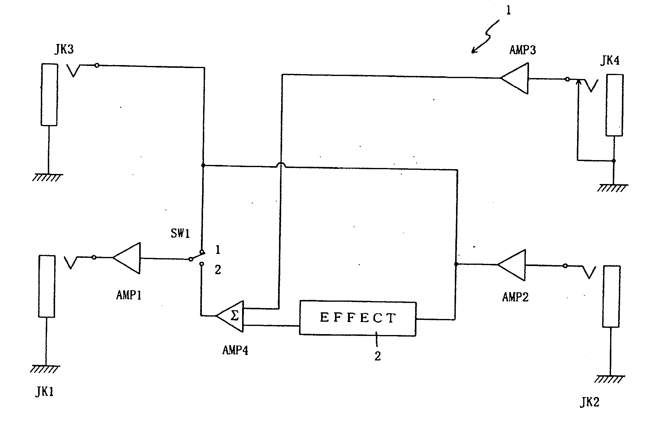
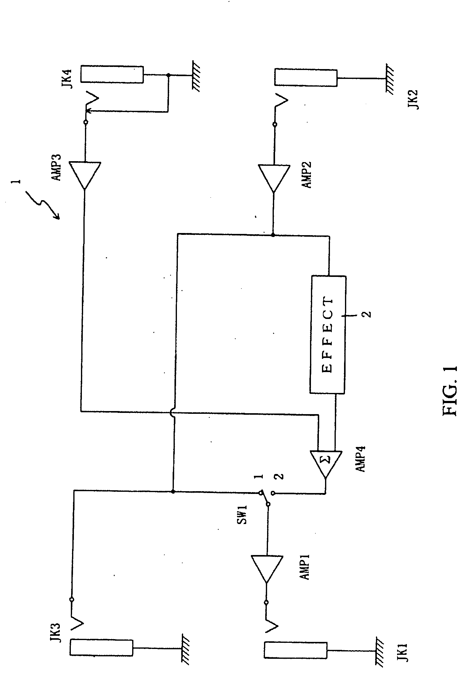
[0036]FIG. 1 is a block diagram that depicts the electrical configuration of an effect device 1 based on the invention. The effect device 1 includes: Input Jack JK 2; Amplifier AMP 1; Amplifier AMP 2; Amplifier AMP 3; Amplifier AMP 4; Switch SW 1; Effect Add Circuit 2; Output Jack JK 1; Send Jack JK 3; and Return Jack JK 4.
[0037]Input Jack JK 2 may comprise a traditional device that receives a plug on one end of a connecting cord that connects with an electric guitar, synthesizer, or other suitable instruments, so that the musical sound signals from the electric guitar; synthesizer, or other suitable instruments will be inputted.
[0038]Amplifier AMP 1, Amplifier AMP 2, and Amplifier AMP 3 may be buffers. Amplifier AMP 4 mixes the musical sound signals that are input from two inputs, and outputs them. Effect Add Circuit 2, may be configured, for example like traditional devices, to give input musical sound signals such effects as distortion or delay.
[0039]The musical sound signals tha...
third embodiment
[0054]As shown in FIG. 4, Effect Device 1 of the third embodiment is equipped with Switch SW 3 that can switch three circuits (Circuit A, B, and C) all at the same time. Circuit A selects the musical sound signals that are input from Return Jack JK 4 and output from Amplifier AMP 3, to connect to either the input of Amplifier AMP 4 (1 Side) or to the Terminal 2 of Circuit C which then switches the connection with the Output Jack JK 1 (2 Side).
[0055]Circuit B selects the output of Jack JK 3 to be either the musical sound signals that were the input of the Input Jack JK 2 and the output of the Amplifier AMP 2 (1 Side), or the musical sound signals that were output to Amplifier AMP 1 (2 Side). Circuit C switches the connection for Output Jack JK 1, and selects either the musical sound signals that were output from the Amplifier AMP 1 (1 Side), or the musical sound signals that are inputted from Return Jack JK 4 which are connected with Terminal 2 of Circuit A and are outputted from Amp...
fourth embodiment
[0066]FIG. 5 refers to a block diagram that shows an electrical configuration of an Effect Device 1 based on a Again for those sections that are identical with the Effect Device 1 of the previously presented embodiments, the descriptions are omitted and same marks are used. Only the sections that are different from the previous embodiments are described.
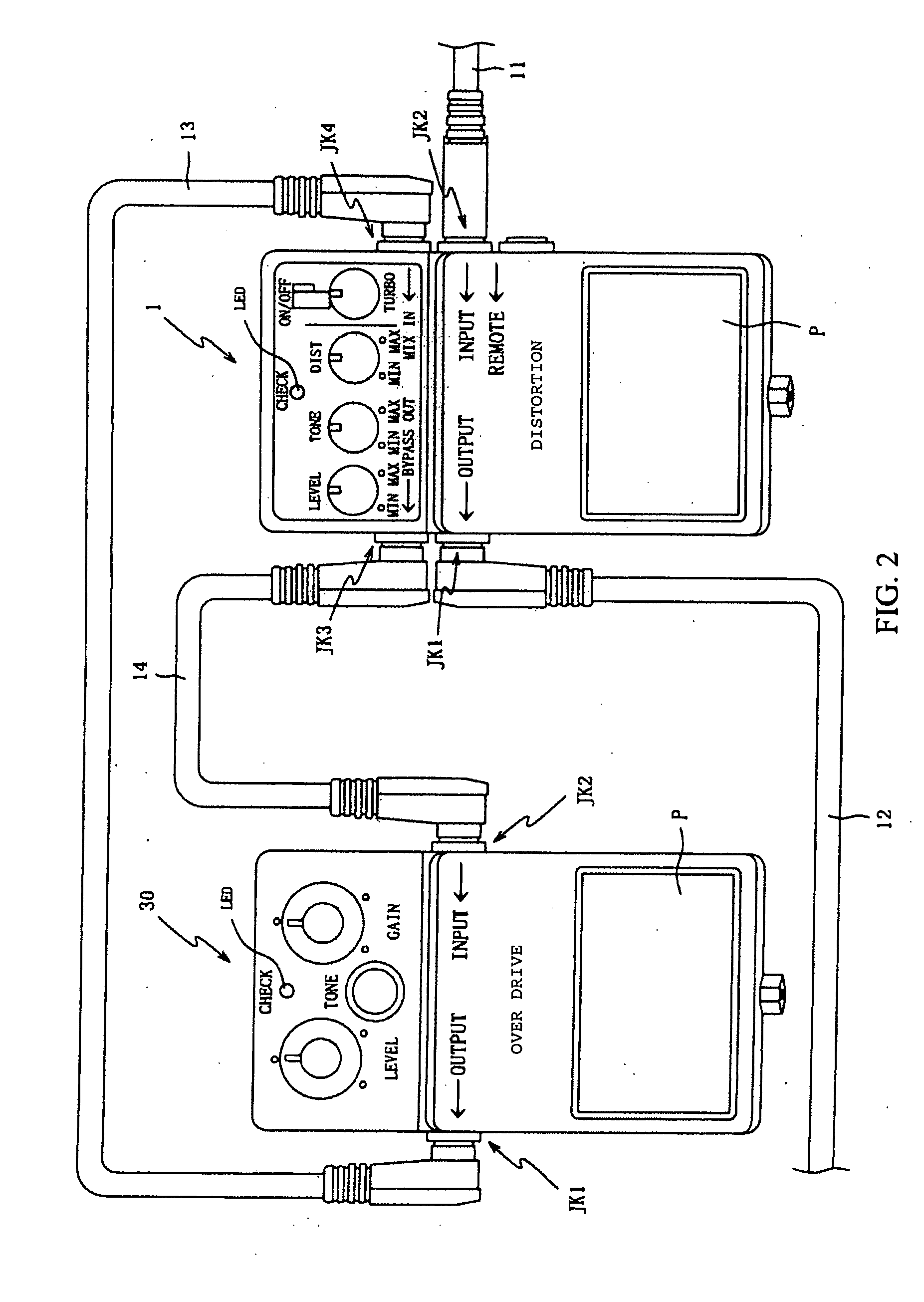
[0067]In a third embodiment, Switch SW 4 enables the device bypass the internal Effect Add Circuit 2 so that only the externally-connected Effect Device 30 adds effect under a series mode and then directly outputs the musical sound signals that were input on Input Jack JK 2 under parallel mode.
[0068]In this fourth embodiment, when the internal Effect Add Circuit 2 does not add effect with switching Switch SW 4, the device can have only the externally-connected Effect Device 30 add effect, regardless of the series mode or the parallel mode.
[0069]In this embodiment, the device is equipped with Switch SW 4 which switches two circuits (...
PUM
 Abstract
Description
Claims
Application Information
 - R&D
- Intellectual Property
- Life Sciences
- Materials
- Tech Scout
- Unparalleled Data Quality
- Higher Quality Content
- 60% Fewer Hallucinations
Browse by: Latest US Patents, China's latest patents, Technical Efficacy Thesaurus, Application Domain, Technology Topic, Popular Technical Reports.
© 2025 PatSnap. All rights reserved.Legal|Privacy policy|Modern Slavery Act Transparency Statement|Sitemap|About US| Contact US: help@patsnap.com


