
Pneumatic sealing ring having an inner tube and expandable liner for a tube-type tire

a technology of pneumatic sealing and inner tube, which is applied in the direction of tyre beads, transportation and packaging, and multiple inflatable chambers, can solve the problem that the inner tube cannot provide run flat support, and achieve the effect of efficient sealing

Active Publication Date: 2007-11-08
DOUGLAS JEFFREY P
View PDF4 Cites 9 Cited by
  • Summary
  • Abstract
  • Description
  • Claims
  • Application Information

AI Technical Summary

Benefits of technology

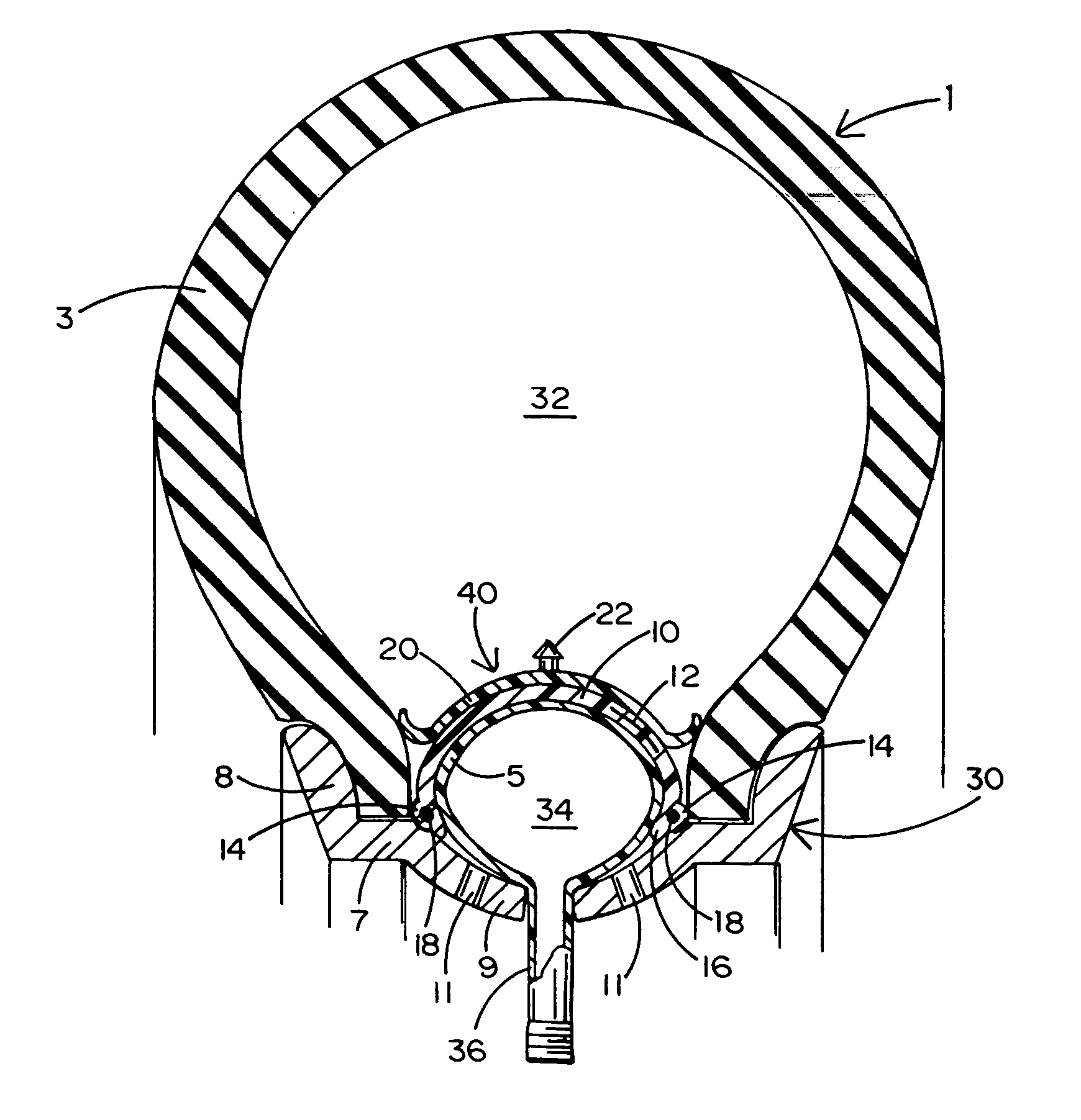
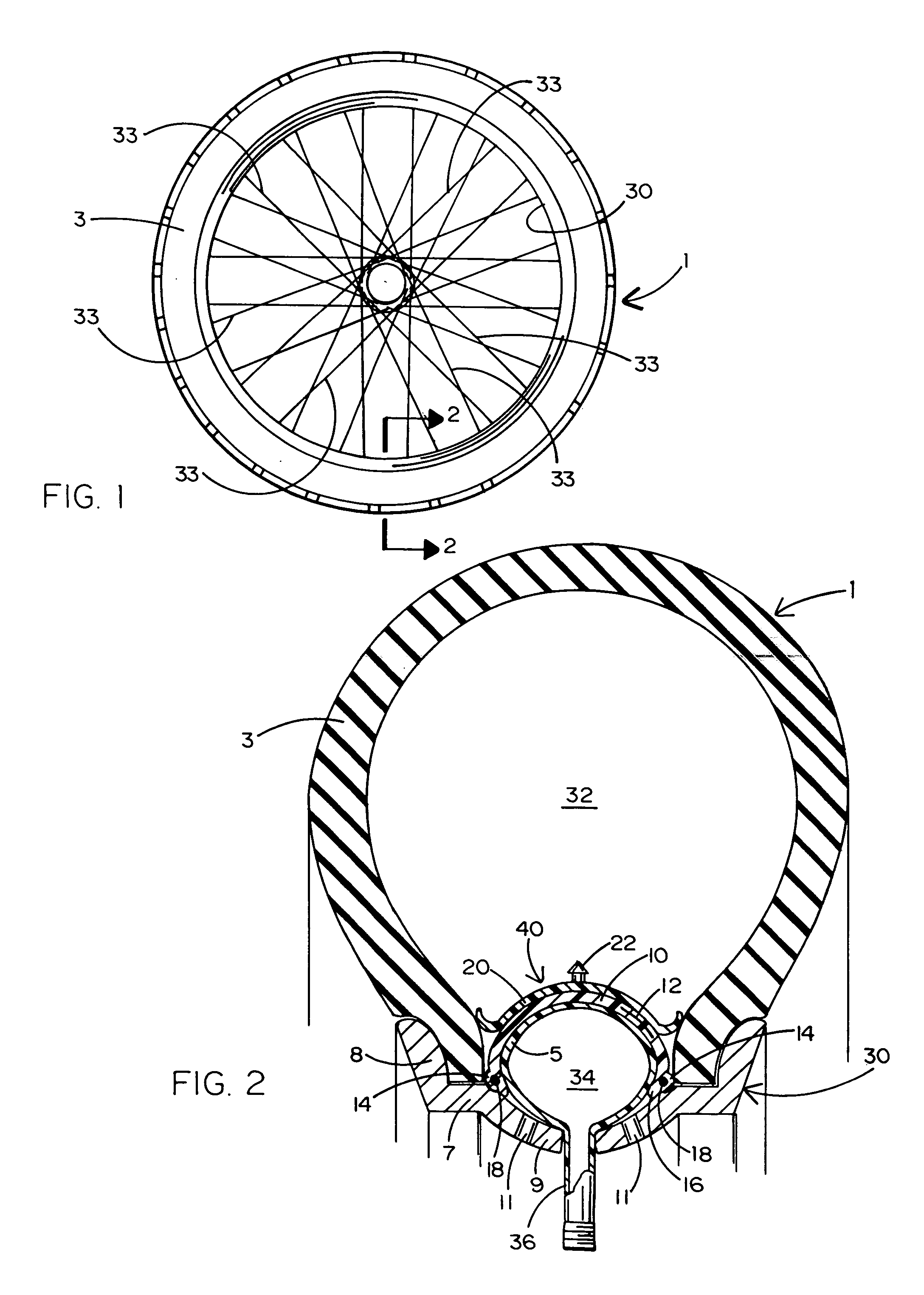
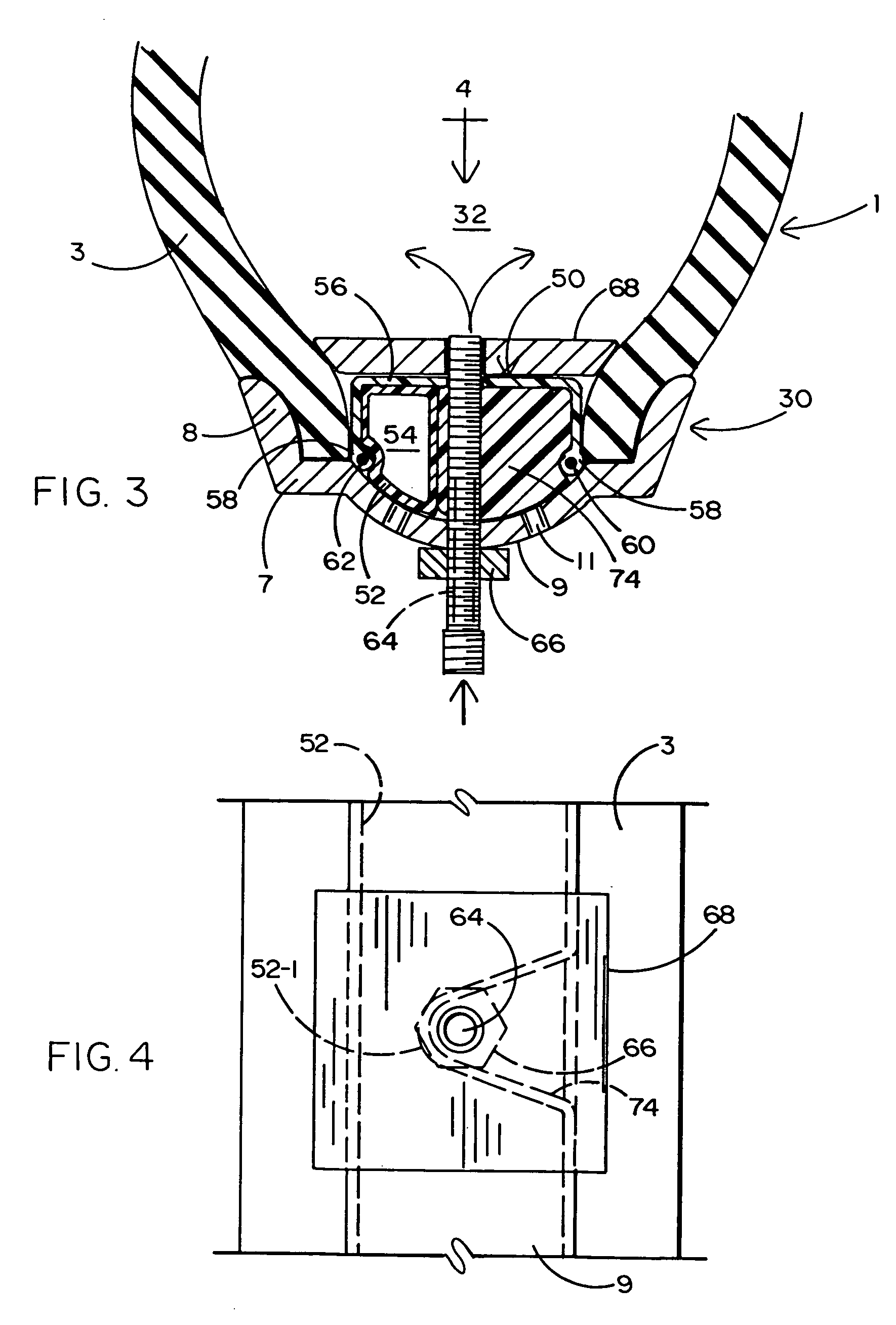
[0008] The main tire section is seated upon the shelf of the rim, and the inner tube of the pneumatic sealing ring is seated upon the beadwell of the rim such that the air chamber of the main tire section is isolated from the rim. The sealing ring also includes an outer liner that is disposed in surrounding engagement over the inner tube. The liner is manufactured from a resilient material that is adapted to expand in response to the air chamber of the inner tube being inflated. Flexible casing cords run around the liner to provide structural reinforcement when the liner is expanded. The outer liner of the pneumatic sealing ring is moved into sealing engagement with the main tire section of the tire as the air chamber of the inner tube is inflated. To this end, one or more sealing rings project outwardly from the side walls of the outer liner to form an efficient seal with the main tire section and force the main tire section against the vertical lip of the rim. A centering lip projects downwardly from each side wall to be seated against the beadwell of the rim and thereby enable the liner to be self-centering over and around the inner tube.

Problems solved by technology

The pneumatic sealing ring includes a thin inner tube having a relatively small volume air chamber, whereby the inner tube is incapable of providing run flat support.

Method used


Image

  • Pneumatic sealing ring having an inner tube and expandable liner for a tube-type tire
  • Pneumatic sealing ring having an inner tube and expandable liner for a tube-type tire
  • Pneumatic sealing ring having an inner tube and expandable liner for a tube-type tire

Examples


Embodiment Construction

[0017] A first preferred embodiment for a pneumatic sealing ring 40 which forms the present invention for use with a tube-type tire 1 and a suitable rim 30 is described while referring to FIGS. 1 and 2 of the drawings. The tube-type tire 1 includes an outer inflatable main tire section 3. The pneumatic sealing ring 40 includes an inflatable inner tube 5 which extends circumferentially around the rim 30 inside the main tire section 3. The main tire section 3 is typically manufactured from thick rubber. The inner tube 5 of sealing ring 40 is preferably manufactured from a relatively thin (e.g., butyl) rubber material or a similar membrane. The tire 1 to which the sealing ring 40 will be mated is ideally mounted on a metal rim 30 having a generally flat shelf 7 located between an upturned vertical lip 8 and a downturned arcuate beadwell 9.

[0018] The main tire section 3 of the tube-type tire 1 is seated on the shelf 7 of the rim 30 so as to press against the vertical lip 8 thereof. The...


PUM


Abstract

A tube-type tire to be mounted on the rim of a (e.g., spoke-type) wheel such as that commonly used by a bicycle or a motorcycle, whereby the tube-type tire will operate without a conventional inner tube and as if it were tubeless. The tire includes a main tire section that is seated upon the generally flat shelf of the rim and a pneumatic sealing ring having an inner tube that is seated upon the beadwell of the rim. An air chamber of the inner tube of the sealing ring is inflated to a greater pressure than an air chamber of the main tire section so as to isolate the air chamber of the main tire section from the rim and force the main tire section against the vertical lip of the rim. The sealing ring also has an outer inflatable liner that is located in surrounding engagement with the inner tube to separate the inner tube from the air chamber of the main tire section. The outer liner has one or more O-ring seals projecting outwardly from the side walls thereof and a centering lip projecting downwardly from the side walls. The O-ring seals are moved into sealing engagement with the inside of the main tire section when the air chamber of the inner tube is inflated and the liner is expanded. The centering lips of the liner are seated upon the beadwell of the rim to cause the liner to be automatically centered over the inner tube.

Description

BACKGROUND OF THE INVENTION [0001] 1. Field of the Invention [0002] This invention relates to pneumatic sealing ring including an inner tube and an expandable liner extending in surrounding engagement thereover to be used with a tube-type tire and rim so that the tube-type tire will operate without a conventional inner tube and as if it were tubeless. [0003] 2. Background Art [0004] A conventional tube-type tire is commonly known to have an inner tube associated therewith. A primary disadvantage of such a tube-type tire is that the rubber material of the inner tube is subject to pinching during use. Such a pinch may result in a tear and, ultimately, a pinch flat, whereby to place the tire out of service or in need of repair. The tools that are commonly used when a new tube-type tire is installed can also cause a pinch in the inner tube and the resulting damage to the tire. [0005] In this same regard, the inner tube associated with the conventional tube-type tire is characteristicall...

Claims


Application Information

Patent Timeline
IPC IPC(8): B60C5/22B60C5/00B60C19/04
CPCB60C5/142B60C5/16B60C15/028Y10T152/10747Y10T152/10522Y10T152/10594B60C15/032
Inventor DOUGLAS, JEFFREY P.
Owner DOUGLAS JEFFREY P
Learn More