Rotary carton feeder

a feeder and carton technology, applied in the field of packaging systems, can solve the problems of limiting the size or range of cartons that can be fed and/or deposited into the flights of the carton conveyor, and achieve the effect of reducing the size of the carton and the range of the carton

Active Publication Date: 2007-11-08
GRAPHIC PACKAGING INT
View PDF53 Cites 24 Cited by
  • Summary
  • Abstract
  • Description
  • Claims
  • Application Information

AI Technical Summary

Benefits of technology

[0007] Each of the carton engaging assemblies typically includes a feed bar having one or more spaced vacuum cups mounted therealong. The feed bar is attached to and carried by a linkage arm attached to an associated rocker arm mounted on the central shaft of the feeder so as to move or orient the vacuum cups of each carton engaging assembly into an attitude to engage the cartons as each carton engaging assembly is moved about its path of travel about the feeder. The feed bar further generally is attached to a feed bar arm, which itself is connected at its opposite end to a pinion gear. The pinion gear of each carton engaging assembly engages a segment gear that is mounted on a cam arm having a cam follower at its free or distal end. The cam follower rides along the cam track formed in at least one of the feeder supports, so as to cause a pivoting or rotating movement of the segment gear, which in turn engages and rotates the pinion gear. As a result, the operating or approach angle of the vacuum cups with respect to the carton face to be engaged by the vacuum cups is amplified.
[0008] Accordingly, as the vacuum cups of each of the carton engaging assemblies approach the cartons contained within the magazine, the vacuum cups are moved into a position to engage the forward, flat face of the next carton within the magazine. At the same time, the radial position of the vacuum cups is controlled and varied by the rotation of the pinion gear attached to the feed bar arm upon engagement with its segment gear. As a further result of the cooperative action of the gear mechanism and oscillating movement of the rocker element, the dwell time of the engagement of the vacuum cups with the front face of the carton being picked can be increased to enable a greater draw or picking of the carton radially inwardly and away from the magazine to ensure that the cartons will be picked cleanly from the magazine, even where taller or thinner cartons are being engaged.
[0009] Thereafter, as the carton is pivoted downwardly toward the carton conveyor, the opening of the carton is initiated. As the carton is moved into engagement with the front or forwardmost lugs of a selected flight of the carton conveyor, the continued forward movement of the feeder running at a slightly faster speed than the movement of the carton conveyor causes the carton to engage the lugs and be opened as the carton is deposited between the lugs of the selected flight. As the carton is substantially opened, the vacuum applied thereto by the vacuum cups generally can be discontinued as the vacuum cups thereafter are moved upwardly and away from the carton face to avoid engagement with the front lugs of the flight. In addition, one or more skids and / or hold down elements can be attached to the feeder and feed bar of each carton engaging assembly, respectively, to engage and bear against the carton to help maintain the carton in an opened configuration as it is carried away by the carton conveyor.

Problems solved by technology

Such conventional rotary feeders tend to have a fixed geometry, however, which limits their path of movement, and thus limits the size or range of sizes of cartons that can be fed and / or deposited into the flights of the carton conveyor.

Method used


Image

  • Rotary carton feeder
  • Rotary carton feeder
  • Rotary carton feeder

Examples


Embodiment Construction

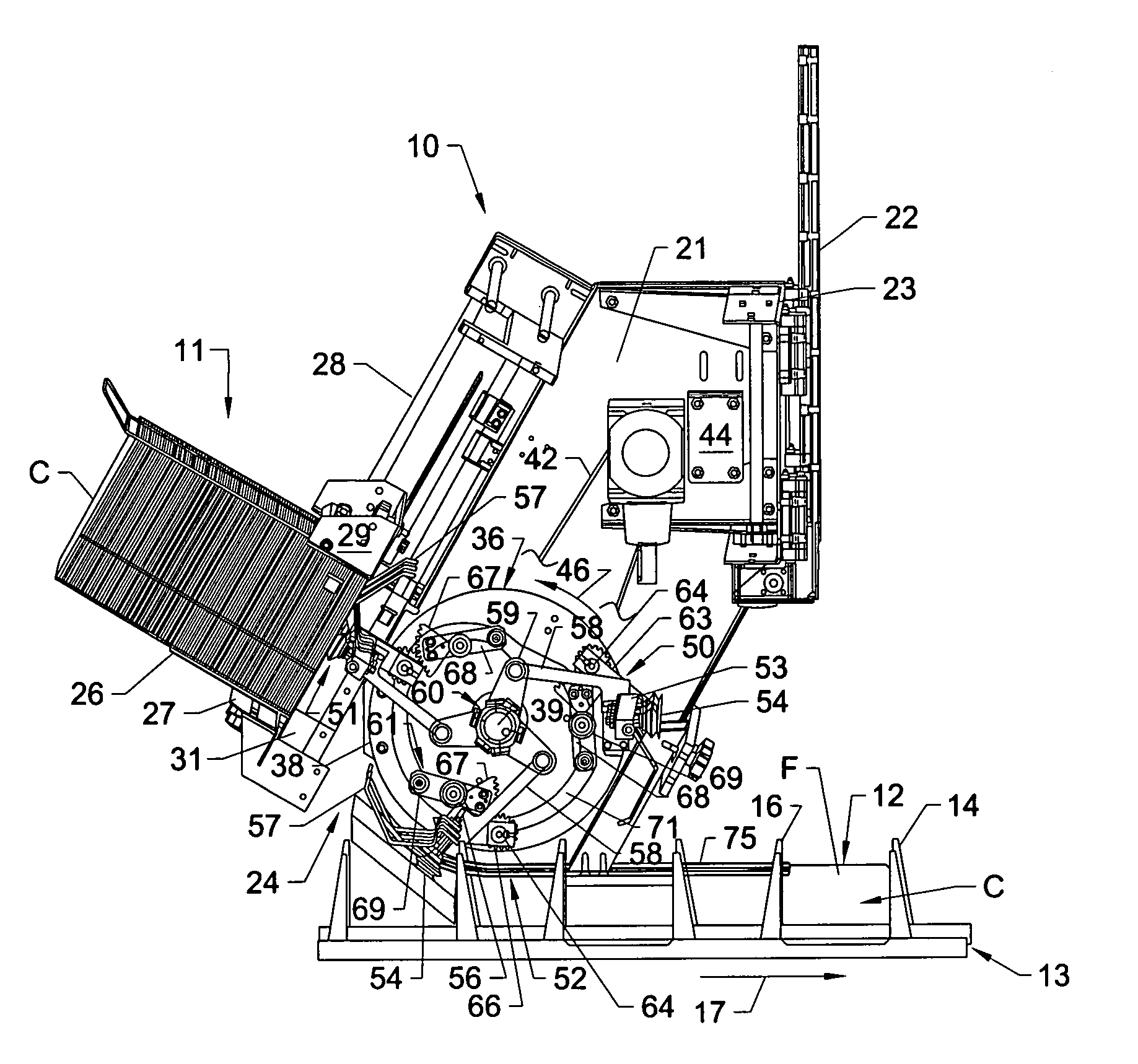
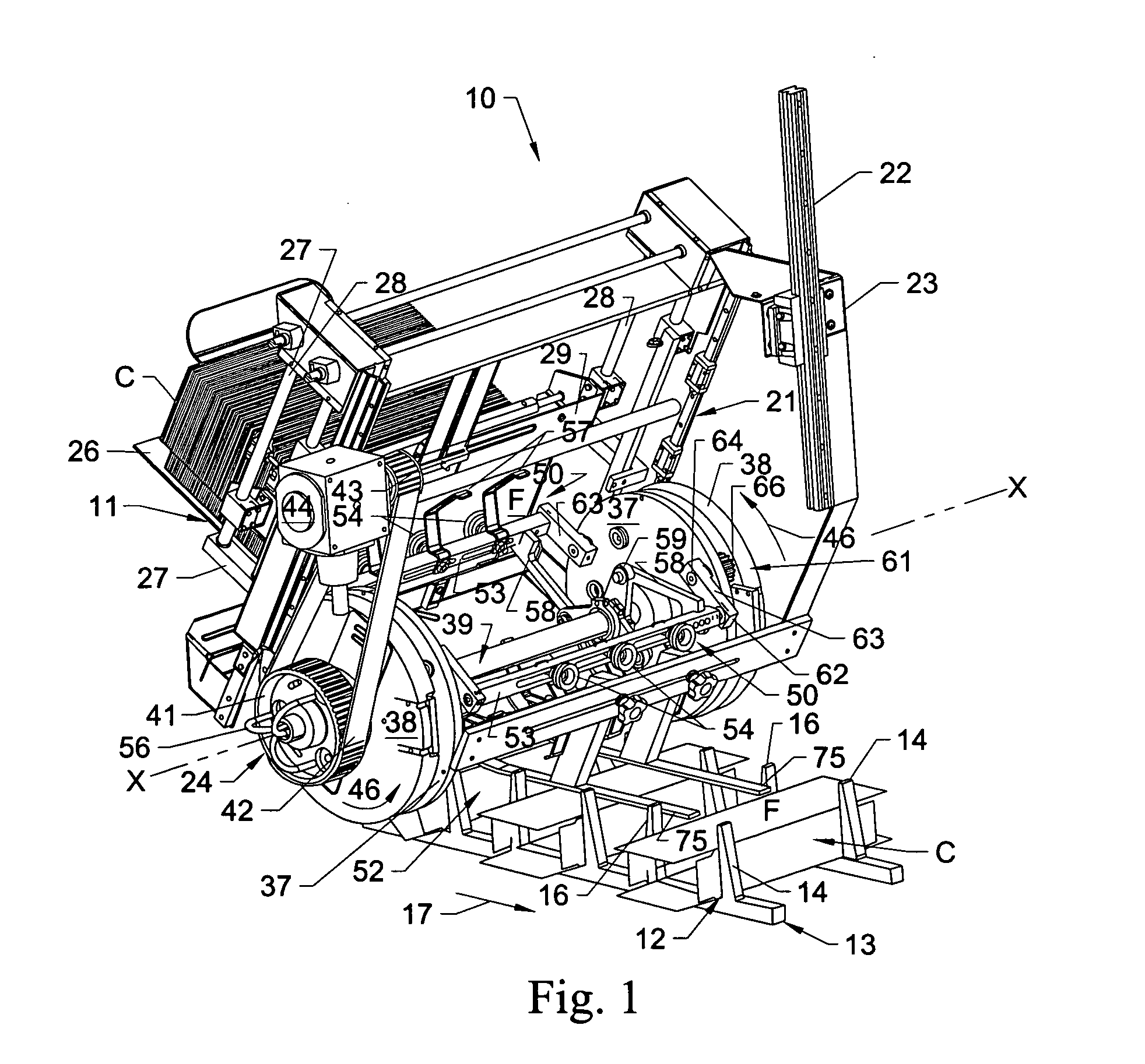
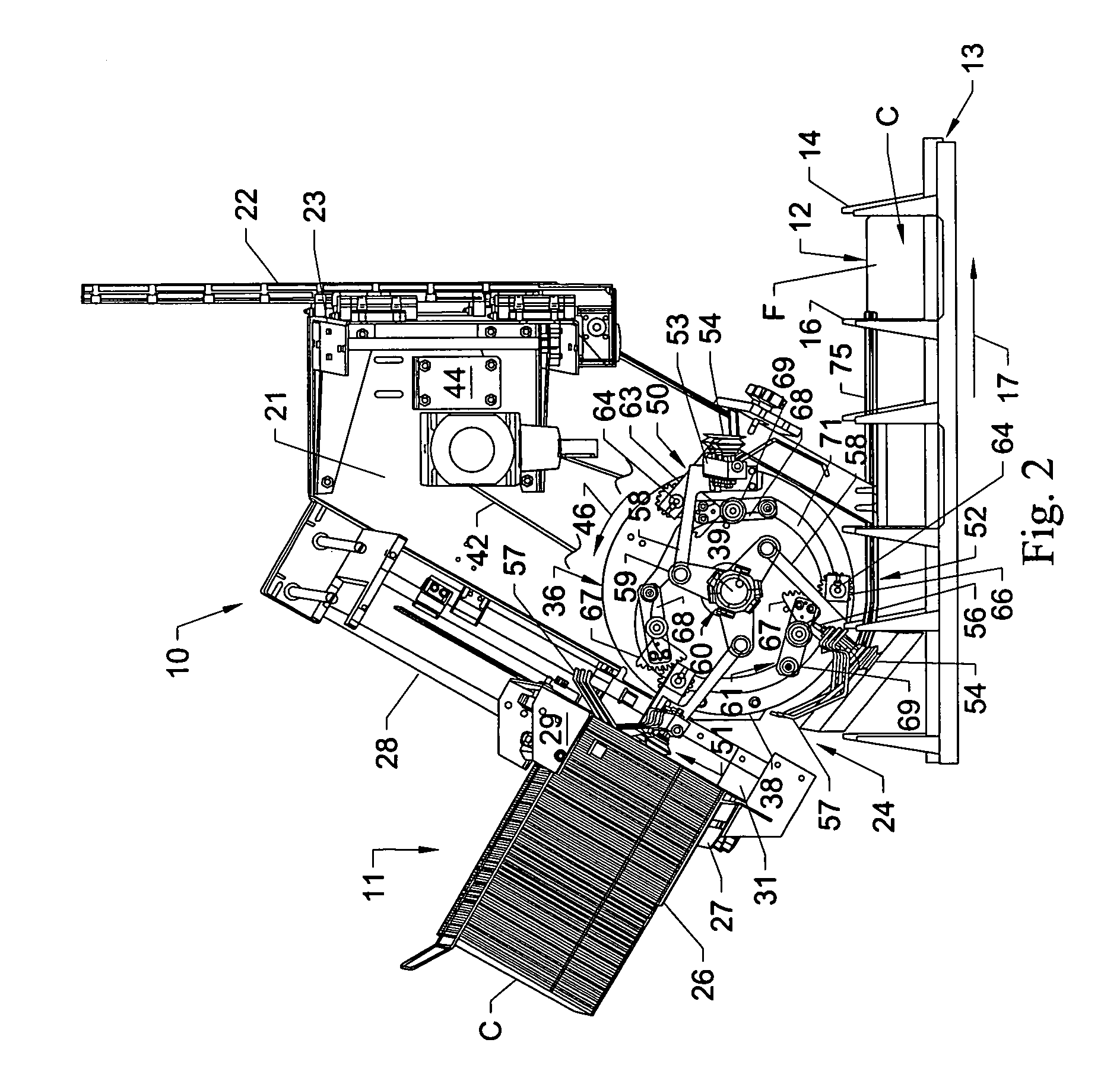
[0016] Referring now to the drawings in which like numerals indicate like parts throughout the several views, FIGS. 1-5 illustrate the system and method for feeding cartons according to the principles of the present invention. As generally illustrated in FIGS. 1-4, the system for feeding cartons of the present invention generally includes a rotary feeder 10 that engages and picks cartons C from a supply of cartons stacked in a generally flat lying attitude within a magazine 11, or similar carton support. The cartons C thereafter are opened and deposited within the flights 12 of a flighted conveyor such as a carton conveyor 13 for a packaging machine (not shown) as the rotary feeder is rotated. The cartons typically are paperboard cartons for use in packaging articles such as cans, bottles, pouches, or other product, although other similar types of articles also can be fed. The cartons generally will be picked from the magazine and opened or unfolded into an opened ended sleeve confi...


PUM


Abstract

A carton feeding system for feeding a series of cartons into selected flights of a carton conveyor is disclosed. The carton feeding system generally includes a rotary feeder having a series of carton feeding assemblies rotated thereabout. The carton engaging assemblies are attached to a gearing system or mechanism that controls the operating angle of the carton engaging assemblies as they engage or pick the cartons from a magazine or supply. Thereafter, the cartons are erected within the flights of a carton conveyor moving beneath the rotary feeder as the carton engaging elements are carried about their path of travel.

Description

FIELD OF THE INVENTION [0001] The present invention generally relates to packaging systems for packaging articles in containers or cartons. In particular, the present invention relates to a carton feeding system for consistently picking, opening, and depositing cartons within the flights of a flighted conveyor, which feeder is able to accommodate a range of varying sizes and / or configurations of cartons. BACKGROUND OF THE INVENTION [0002] In the automated packaging of goods such as soft drink cans, pouches, and other similar products into cartons or boxes, the cartons typically can be fed from a stack or supply of preglued carton sleeves, opened, and deposited on a carton conveyor prior to being fed into a product packaging machine. The cartons generally will be deposited within the flights of a carton conveyor with the products thereafter being inserted through the open ends of the carton sleeve. Thereafter, the end flaps of the cartons are folded and typically adhesively attached ...

Claims


Application Information

Patent Timeline
Patent Type & Authority Applications(United States)
IPC IPC(8): B65H3/40B31B50/80
CPCB65B43/185
Inventor FORD, COLIN
Owner GRAPHIC PACKAGING INT
Why Eureka
Try Eureka