Amusement ride
a technology for amusement rides and rides, applied in amusements, entertainment, rolling drums, etc., can solve the problems of large tower structure with prolonged downtime, limited customer service capacity of free-fall towers, and prominent but sometimes unwanted dominance, and achieve the effect of convenient transportation
- Summary
- Abstract
- Description
- Claims
- Application Information
AI Technical Summary
Benefits of technology
Problems solved by technology
Method used
Image


Examples
first embodiment
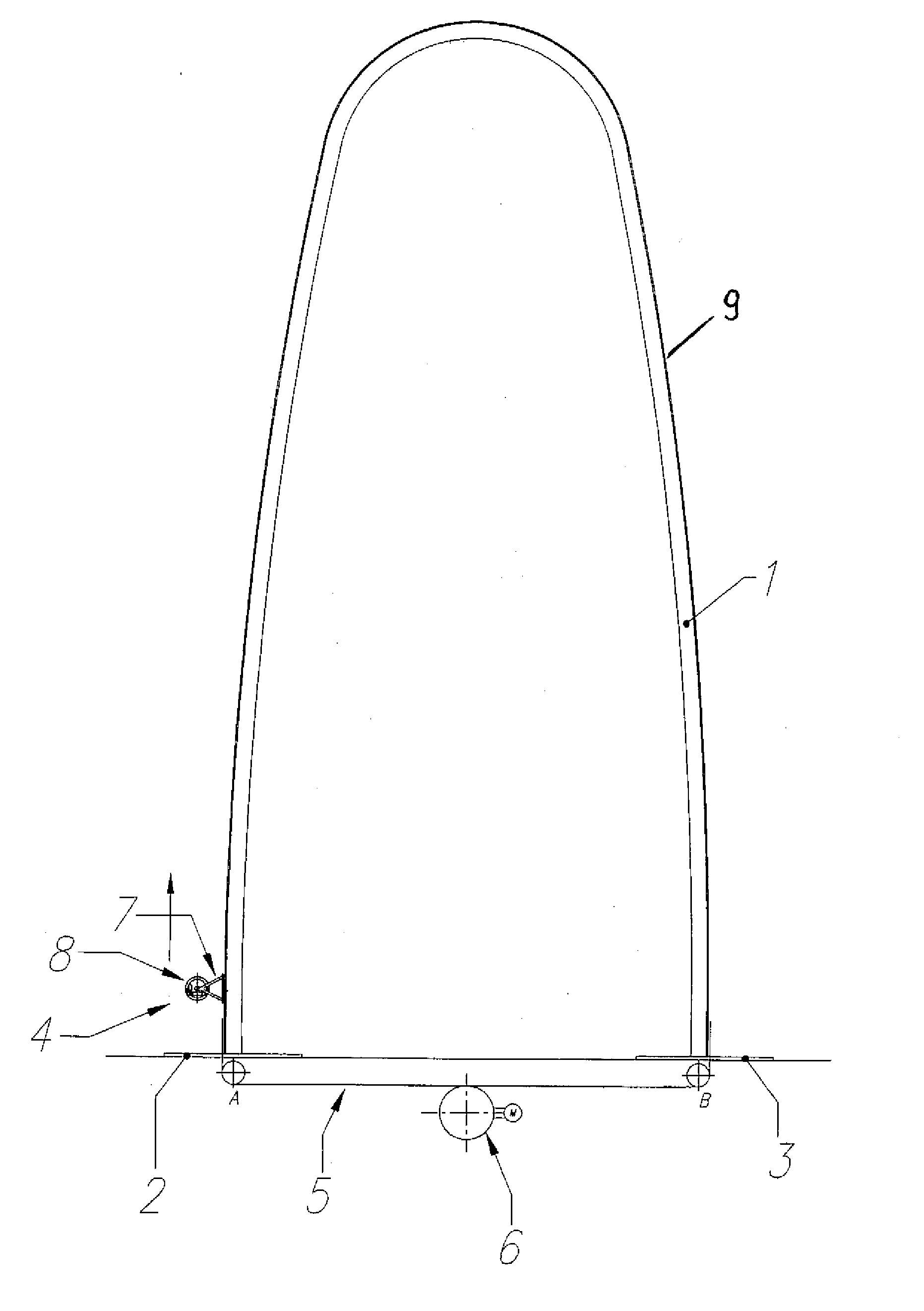
[0033] Turning now to the drawing, and in particular to FIG. 1, there is shown a schematic side view of an amusement ride according to the present invention, including a support structure 1 having the shape of a vertical standing arch that spans from a first ground base 2 to a second ground base 3. A vehicle 4 is movably supported on the structure 1 for carrying one or more passengers at least partially along the length of the support structure 1 from an initial loading position at the first ground base 2.
[0034] A cable 9 is affixed to the vehicle 4 and runs along the length of the structure 1 and returns via a link 5 from the first ground base 2 to the second ground base 3. In the embodiments shown here, the link 5 is designed as an underground tunnel.
[0035] A motor 6 is provided to act upon the cable 9 as it runs along the link 5 from the first ground base 2 to the second ground base 3. Together with the motor 6, the cable 9 acts as a lifting mechanism for lifting the vehicle 4 f...
second embodiment
[0039] FIGS. 4 to 6 show an amusement ride according to the present invention. Parts corresponding with those in FIG. 1 are denoted by identical reference numerals and not explained again. The description below will center on the differences between the embodiments. In this embodiment, provision is made for two vehicles 4, 4a that travel in opposite directions. As shown in FIG. 4 the vehicle 4 is in a loading position, while the second vehicle 4a is held at an elevated position, giving the passengers a prolonged bird's-eye view. After loading new passengers, vehicle 4 travels upwards along the first leg of the arch-shaped support structure 1, while the second vehicle 4a travels downwards on the second leg of the arch-shaped structure towards the second ground base 3. Reaching the second ground base 3, passengers can disembark from the second vehicle 4a and new passengers can embark this vehicle 4a, while the passengers in the first vehicle 4 can enjoy a prolonged view from the bird'...
third embodiment
[0040]FIG. 7 shows an amusement ride according to the present invention. Parts corresponding with those in FIG. 1 are denoted by identical reference numerals and not explained again. The description below will center on the differences between the embodiments. In this embodiment, the lifting device for operating the vehicle 4 is arranged at the first ground base 2. A motor 6 can wind or unwind the cable 9 which is fixed to the vehicle 4 and can thereby lift and—if the motor 6 is used as a generator—slow down the vehicle 4.
PUM
 Abstract
Description
Claims
Application Information