Shunting type pwm dimming circuit for individually controlling brightness of series connected leds operated at constant current and method therefor

Inactive Publication Date: 2007-11-15
MICROCHIP TECH INC
View PDF4 Cites 202 Cited by
  • Summary
  • Abstract
  • Description
  • Claims
  • Application Information

AI Technical Summary

Benefits of technology

[0005]In accordance with one embodiment of the present invention, a dimming circuit for driving a string of LEDs at constant current is disclosed. The dimming circuit has a power converter. A control circuit is coupled to the power converter. A plurality of shunt switches is provided. An individual shut switch is coupled to each LED. Each LED can be shunted individually by the individual shunt switch. The control circuit corrects an internal DC state based on a feedback signal VO so that the output current of the power converter remains unchanged when at least one LED is shunted.
[0006]In accordance with another embodiment of the present invention, a dimming circuit for individual controlling brightness of series-connected LEDs driven at constant current is disclosed. The dimming circu

Problems solved by technology

Furthermore, prior art circuits have several issues relating to slow PWM dimmi

Method used


Image

  • Shunting type pwm dimming circuit for individually controlling brightness of series connected leds operated at constant current and method therefor
  • Shunting type pwm dimming circuit for individually controlling brightness of series connected leds operated at constant current and method therefor
  • Shunting type pwm dimming circuit for individually controlling brightness of series connected leds operated at constant current and method therefor

Examples


Embodiment Construction

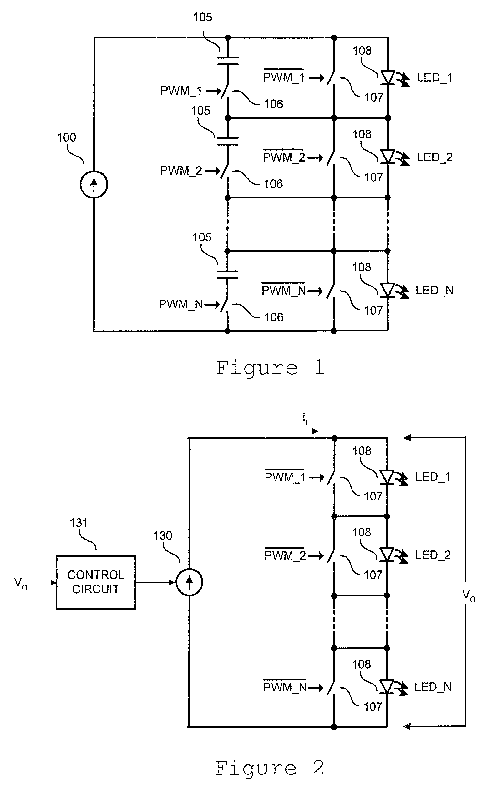
[0018]Referring to FIG. 1, a power supply circuit for driving a string of LEDs 108 at constant current is shown. Power to the LED string is supplied from a switching power converter 100 operating in a constant DC output current mode. There is little or no smoothing capacitor assumed at the output of the power converter 100. Thus, the output current of the power converter 100 is assumed to have a significant AC ripple component. The AC ripple is further filtered using smoothing capacitors 105.

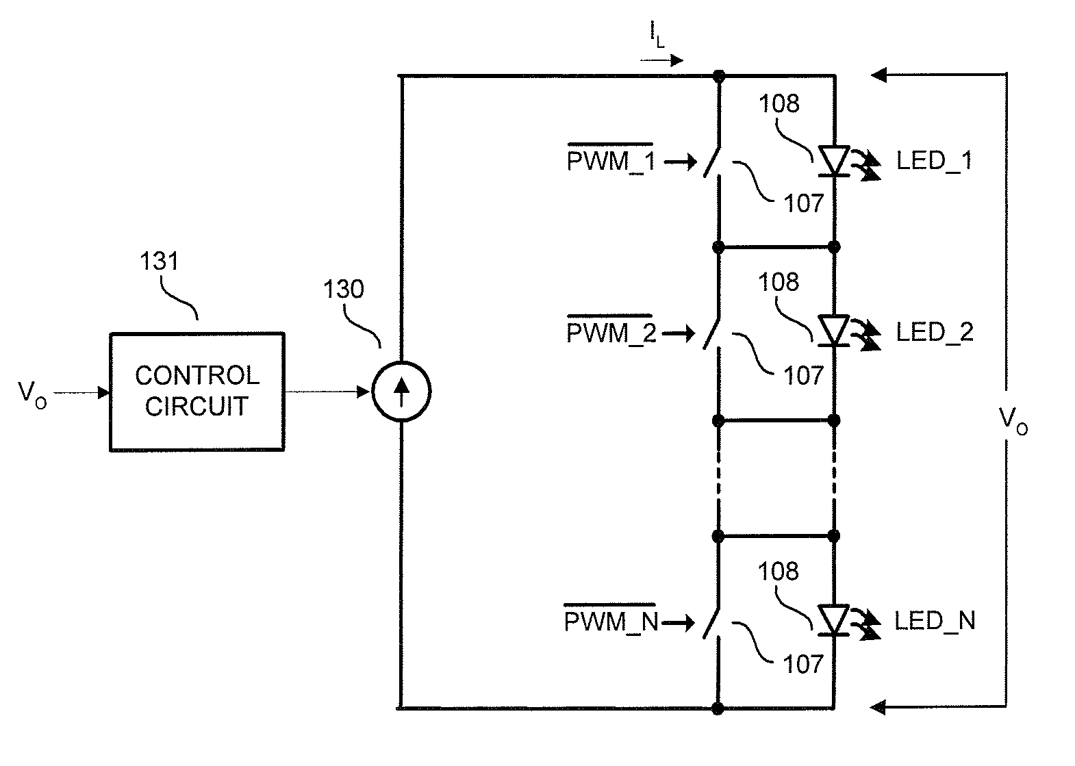
[0019]Each LED 108 is equipped with an independently controlled switch 107 adapted to shunt the corresponding LED 108. Brightness of each LED 108 is individually controlled by periodically shunting it using the corresponding switch 107. Each switch 107 is controlled by external periodical dimming signals PWM_1 through PWM_N having controlled duty ratios.

[0020]Switches 106 are included in series with each smoothing capacitor 105 for disconnecting the capacitor 105 from the LED 108. The switches 1...


PUM


Abstract

A dimming circuit for driving a string of LEDs at constant current has a power converter. A control circuit is coupled to the power converter. A plurality of shunt switches is provided. An individual shut switch is coupled to each LED. Each LED can be shunted individually by the individual shunt switch. The control circuit corrects an internal DC state based on a feedback signal VO so that the output current of the power converter remains unchanged when at least one LED is shunted.

Description

RELATED APPLICATION[0001]This application is related to U.S. Provisional Application Ser. No. 60 / 747,250, filed May 15, 2006, in the name of the same inventors listed above, and entitled, “SHUNTING TYPE PWM DIMMING CIRCUIT FOR INDIVIDUALLY CONTROLLING BRIGHTNESS OF SERIES CONNECTED LEDS OPERATED AT CONSTANT CURRENT”, the present patent application claims the benefit under 35 U.S.C. §119(e).FIELD OF THE INVENTION[0002]The invention relates to a lighting circuit, and specifically to a shunting type PWM dimming circuit for individually controlling brightness of series connected LEDS operated at constant current.BACKGROUND OF THE INVENTION[0003]Recent developments of Light Emitting Diodes (LED) backlights for Liquid Crystal Display (LCD) panel displays in televisions and monitors require driving large arrays of LEDs. In many applications, it is desirable to individually control the brightness level of the LEDs. For optimum performance, high brightness LEDs should be driven by a current ...

Claims


Application Information

Patent Timeline
IPC IPC(8): H05B37/00
CPCH05B33/0818H05B33/0851H05B33/083H05B45/10H05B45/3725H05B45/375H05B45/385H05B45/48
Inventor MEDNIK, ALEXANDERTIRUMALA, ROHIT
Owner MICROCHIP TECH INC
Why Eureka
Try Eureka