Method and system for improved detection of material reflectances in an image

a technology of material reflectance and image, applied in image enhancement, scene recognition, instruments, etc., can solve the problems of distorted image of earth-based objects, received from satellite transmission, etc., and achieve the effect of facilitating correction of effects

Active Publication Date: 2007-11-15
INNOVATION ASSET COLLECTIVE
View PDF10 Cites 5 Cited by
  • Summary
  • Abstract
  • Description
  • Claims
  • Application Information

AI Technical Summary

Benefits of technology

[0005] The present invention utilizes a constancy of a characteristic spectral ratio for an image to faci...

Problems solved by technology

However, images of earth-based objects, received from a satelli...

Method used


Image

  • Method and system for improved detection of material reflectances in an image
  • Method and system for improved detection of material reflectances in an image
  • Method and system for improved detection of material reflectances in an image

Examples


Embodiment Construction

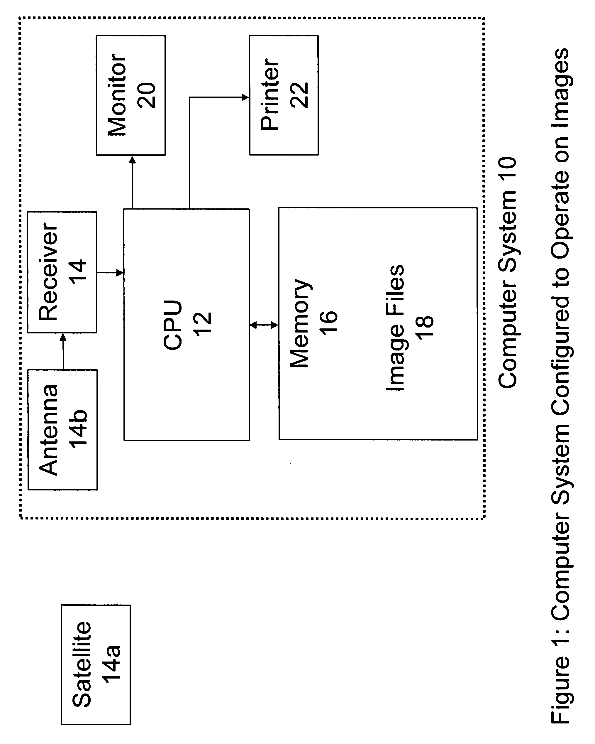
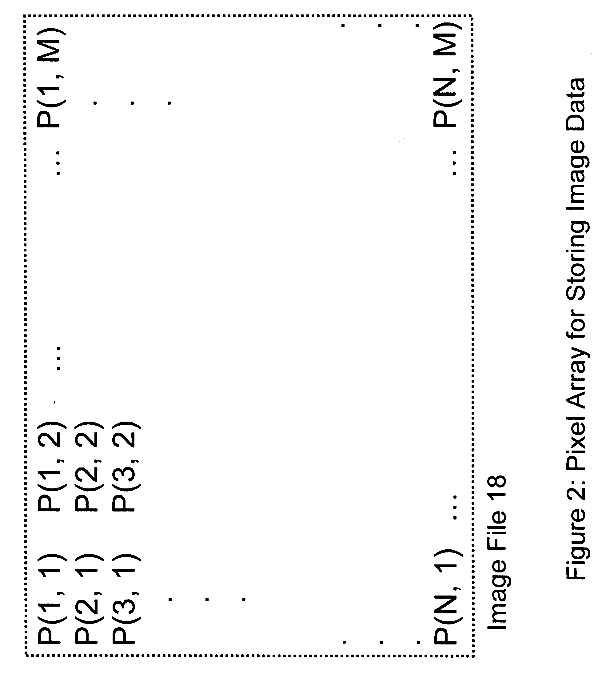
[0013] Referring now to the drawings, and initially to FIG. 1, there is shown a block diagram of a computer system 10 arranged and configured to perform operations related to images. A CPU 12 is coupled to a device such as, for example, a receiver 14 via, for example, a USB port. In our example, the receiver 14 operates to receive image transmissions from a distant source, such as, for example, an orbiting satellite 14a via an antenna 14b. The satellite 14a comprises a sensor such as a camera operated to capture images of the surface of the earth, transform those images into digital image files, and transmit the digital images to the receiver 14, as is generally known. The receiver 14 then operates to download the images to the CPU 12. The CPU 12 stores the downloaded images in a memory 16 as image files 18. The image files 18 can be accessed by the CPU 12 for display on a monitor 20, or for print out on a printer 22. The CPU 12 can be equipped with a real time operating system for ...


PUM


Abstract

In a first exemplary embodiment of the present invention, an automated, computerized method for manipulating an image is provided. The method of the present invention comprises the steps of selecting matched shadow/lit pairs of image portions from each of separate, different materials depicted in the image, utilizing the selected matched pairs to determine spectral ratio information for the image, calculating a correction term as a function of the spectral ratio information and utilizing the correction term to manipulate the image, to remove effects, such as, for example, path radiance.

Description

[0001] This application is a continuation-in-part of application Ser. No. 11 / 431,755, filed May 10, 2006, entitled A Method And System For Removing Path Radiance From An Image. BACKGROUND OF THE INVENTION [0002] Images of earth-based objects are routinely captured by satellites in orbit around earth. These images are used in significant and often critical scientific, military and intelligence operations and studies. Typically, the orbiting satellites transmit captured images to earth-based stations for review and study. However, images of earth-based objects, received from a satellite transmission, are often distorted due to effects of the atmosphere. Light reflected from an earth-based object must travel through a thick layer of relatively dense atmosphere before being received by a sensor on board an orbiting satellite. The air in the atmosphere, as well as substances suspended in the atmosphere, such as water droplets and dust, can scatter light that is captured by a sensor on bo...

Claims


Application Information

Patent Timeline
IPC IPC(8): G06K9/36G06V20/13
CPCG06K9/0063G06T5/50G06K2009/366G06K9/346G06V20/13G06V10/273G06V10/248
Inventor SMITH, CASEY ARTHURFRIEDHOFF, RICHARD MARK
Owner INNOVATION ASSET COLLECTIVE
Why Eureka
Try Eureka