Development device, and image forming apparatus and process cartridge using the development device

a development device and development technology, applied in the field of development devices, can solve the problems of insufficient density of image, inability to develop, and inability to achieve the effect of reducing image density

Inactive Publication Date: 2007-11-15
RICOH KK
View PDF5 Cites 31 Cited by
  • Summary
  • Abstract
  • Description
  • Claims
  • Application Information

AI Technical Summary

Benefits of technology

[0010]According to an aspect of the invention, a development device includes a developer carrying member, a developer supply conveyance path, a developer collection conveyance path, a developer agitation conveyance path, at least one partition member, at least one transfer opening, and a communication opening. The developer carrying member rotates while bearing thereon a two-component developer including a magnetic carrier and a toner. This developer carrying member supplies the toner to a latent image on a surface of a latent image carrier in a development region in which the developer carrying member faces the latent image carrier so as to develop the latent image. The developer supply conveyance path includes a developer supply conveyance member supplying the two-component developer to the developer carrying member so as to convey the two-component developer in a first direction of the developer carrying member. The developer collection conveyance path includes a developer collection conveyance member collecting a developer collected from the developer carrying member passed the opposing position so as to convey the collected developer in the first direction. The developer agitation conveyance path includes a developer agitation conveyance member receiving an excess developer unused for development and the collected developer. The developer agitation conveyance path conveys the excess developer and the collected developer in a second direction opposite to the first direction while agitating the developers, and supplies the agitated developers to the developer supply conveyance path. The at least one partition member separates the developer collection conveyance path, the developer supply conveyance path, and the developer agitation conveyance path from each other. The at least one transfer opening is disposed in the partition member to transfer the collected developer from an end of the developer collection conveyance path at a downstream side relative to the first direction to an upstream side of the developer agitation conveyance path relative to the second direction. The communication opening communicates the developer collection conveyance path with the developer agitation conveyance path. The communication opening is disposed at a further upstream side of the developer collection conveyance path than the at least one transfer opening relative to the first direction and at a higher position than a predetermined height of the developer collection conveyance path.

Problems solved by technology

In other words, the image density of an image varies at the upstream side and downstream side in the developer conveyance direction of the conveyance path in which the developer is supplied to the developer carrying member, resulting in generation of an uneven density image.
This immediate supply of the collected developer causes inadequate agitation of the developer, resulting in non-uniform charging of the toner, thereby decreasing of the image density even if the toner density is maintained at an appropriate level.
In this case, the collected developer in the collection conveyance path is re-supplied to the developer carrying member, resulting in an occurrence of a problem in that the collected developer having an inappropriate toner density (i.e., the toner is consumed) is mixed with the developer having an appropriate toner density.
Thereby, the toner density can be decreased, and uneven images can be generated.

Method used


Image

  • Development device, and image forming apparatus and process cartridge using the development device
  • Development device, and image forming apparatus and process cartridge using the development device
  • Development device, and image forming apparatus and process cartridge using the development device

Examples


Embodiment Construction

[0022]In describing exemplary embodiments illustrated in the drawings, specific terminology is employed for the sake of clarity. However, the disclosure of this patent specification is not intended to be limited to the specific terminology so selected and it is to be understood that each specific element includes all technical equivalents that operate in a similar manner.

[0023]Referring now to the drawings, wherein like reference numerals designate identical or corresponding parts throughout the several views, an image forming apparatus according to an exemplary embodiment of the present invention is described.

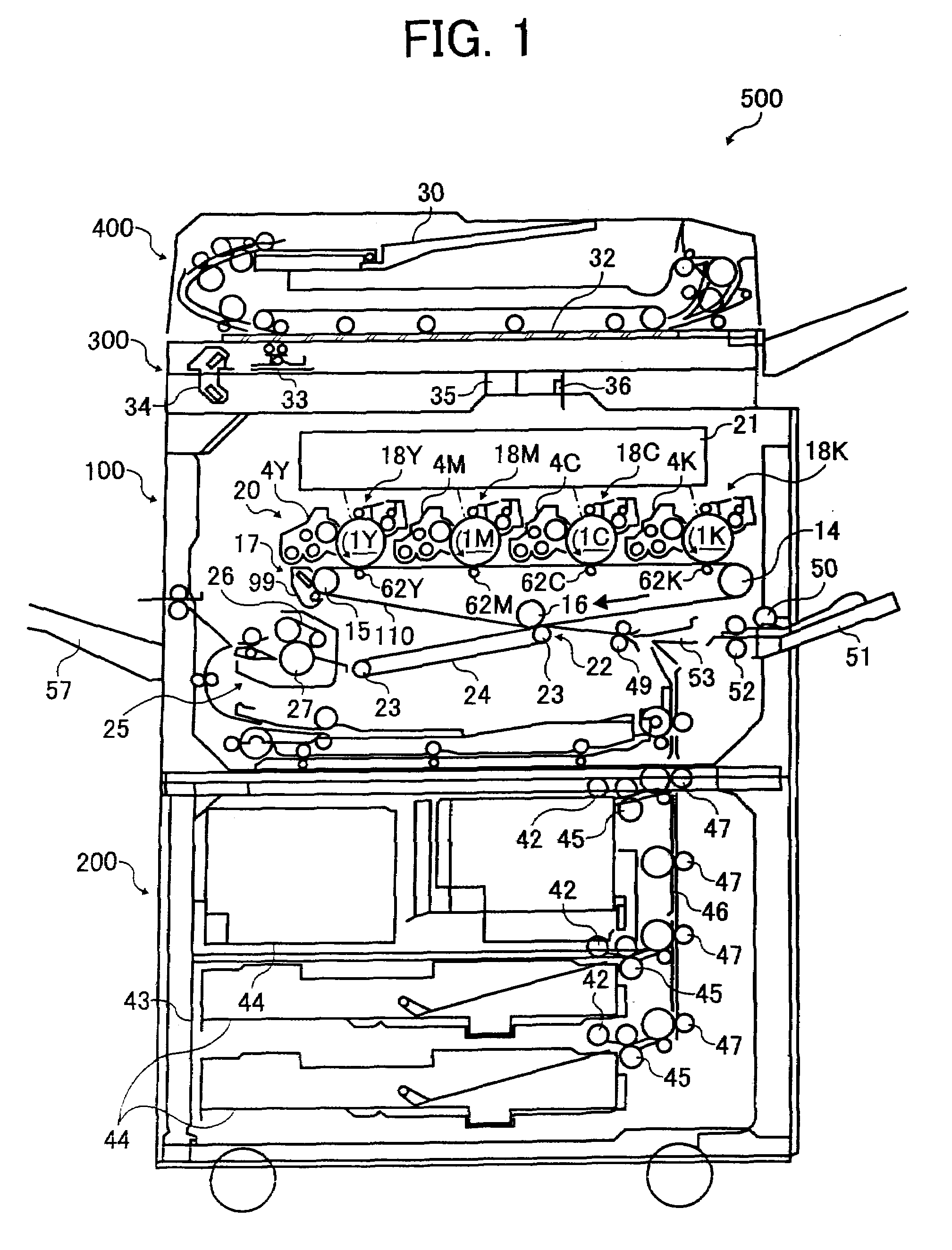
[0024]Referring to FIG. 1, a tandem image forming apparatus 500 having four photoconductor drums 1Y, 1M, 1C and 1K for four colors is illustrated. The image forming apparatus 500 includes a printing unit 100, a sheet feeder 200, a scanner 300 and an automatic document feeder 400.

[0025]The printing unit 100 includes an optical writing unit 21, an image forming unit 20, an inter...


PUM


Abstract

A development device includes a developer carrying member, developer supply, developer collection and developer agitation conveyance paths, transfer and communication openings, and partition. The developer carrying member bears a two-component developer. The developer supply and developer collection conveyance paths respectively convey the two-component and collected developers in the first direction. The developer agitation conveyance path conveys excess and collected developers in a second direction while agitating to supply the agitated developers to the developer supply conveyance path. The partition separates the developer collection, developer supply, and developer agitation conveyance paths. The transfer opening transfers the collected developer from the first to the second direction. The communication opening, disposed at a further upstream side of the developer collection conveyance path than the transfer opening in the first direction and at a higher position than the developer collection conveyance path, communicates the developer collection conveyance path with the developer agitation conveyance path.

Description

CROSS-REFERENCE TO RELATED APPLICATION[0001]This patent application is based on Japanese patent application, No. 2006-135217 filed on May 15, 2006 in the Japan Patent Office, the entire contents of which are incorporated by reference herein.BACKGROUND OF THE INVENTION[0002]1. Field of the Invention[0003]Exemplary aspects of the present invention relate to a development device, and more particularly to a development device using a two-component developer. In addition, the exemplary aspects of the present invention also relate to an image forming apparatus and a process cartridge using a development device.[0004]2. Description of the Related Art[0005]A related art development device, which employs a two-component developer including a toner and a magnetic carrier, for use in an image forming apparatus includes a supply conveyance path and an agitation conveyance path to circulate the developer. The supply conveyance path supplies the developer to a developer carrying member while conv...

Claims


Application Information

Patent Timeline
Patent Type & Authority Applications(United States)
IPC IPC(8): G03G15/08
CPCG03G2215/0822G03G15/0877G03G15/0893G03G2215/0838
Inventor YOSHIDA, SATORUHIROSE, HIROYATSUDA, KIYONORI
Owner RICOH KK
Why Eureka
Try Eureka