
Multi-Pitch Screw and Method and Apparatus for manufacturing Multi-Pitch Screw

Inactive Publication Date: 2007-11-15
NAGOYA INDUSTRIAL SCIENCE RESEARCH INST
View PDF12 Cites 12 Cited by
  • Summary
  • Abstract
  • Description
  • Claims
  • Application Information

AI Technical Summary

Benefits of technology

[0026] According to claim 1 of the invention, side walls 201, 202 of screw threads 20 are alternate and consecutively, alternating between a lead angle obtuse section 201 and a lead angle acute section 202 while rotating along a helix. By forming such multipitch screw, the effective lead of the entire screw becomes an average value of a lead angle obtuse section and a lead angle acute section. The resisting force to loosening of the screw is dominant in the frictional force to the opposite member in the lead angle obtuse section by axial force, and hence a stronger anti-loosening action is realized by the frictional force in the lead angle obtuse section, while maintaining a large effective lead. Side walls 201, 202 of screw threads are formed to be symmetrical to the central line 20c of screw threads. That is, the screw threads and screw grooves are always left and right symmetrical, and the workpiece (bolt 1) can be rolled and processed without generating excessive force to vary its axial center.
[0027] According to claim 2 of the invention, since the lowest position of the screw groove (bottom between screw thread 20 and screw thread 20) 21b has a constant lead angle in a general spiral screw shape, and the leading end portion of the opposite side screw slides in the lowest position 21b, and smooth screw feeding and tightening can be realized. Besides, since the lowest position 21b is always provided in the bottom of the screw groove 210, stability of rolling and processing of a workpiece (bolt 1) is further enhanced.
[0028] According to claim 3 of the invention, both side walls 401, 402 formed alternately and consecutively, alternating between a section 401 departing from a central line 40c of protrusions 440b and an approaching section 402 along the central line 40c, and symmetrically to the central line 440c of protrusions 40b, and by such protrusions 40b for screw threads varying regularly in lead angle, a multipitch screw 20 is rolled around the outer circumference 2 of the shaft-like blank piece 1. In other words, the screw threads and screw grooves are always symmetrical left and right, and rolling and processing can be executed stably without generating excessive force to vary the axial center of the shaft-like blank piece 1.
[0029] According to claim 4 of the invention, protrusions of a flat die 4 include a region 410 for screw threads 40a of a constant lead angle provided linearly, and a region 420 for screw threads 40b of a lead angle varying regularly, provided consecutively to the region 410, and slightly lower in height than the region 410, with both side walls 401, 402 formed alternately and consecutively, alternating a section 401 departing from the central line of protrusions 40b and an approaching section 402, and symmetrically to the center line 40c of protrusions 40b. First by protrusions 40a of the region 410 for screw threads of a constant lead angle, tracks 210 of a constant lead angle screw are formed on the outer circumference 2 of the shaft-like blank piece 1, and successively by protrusions 40b of the region 420 for screw threads of a lead angle varying regularly, tracks of the multipitch screw 20 consecutive between a section 201 of lead angle obtuse and a section 202 of lead angle acute are formed, therefore tracks of a multipitch screw changing in force applied at the time of rolling can be formed easily.
[0030] According to claim 5 of the invention, protrusions 40a, 40b of a flat die 4 include a region 410 for screw threads of a constant lead angle provided linearly, and a region 420 for screw threads of a lead angle varying regularly, provided consecutively to the region 410, and slightly broader in width of the sectional shape than the region 410 and lower in height and provided in stair steps changing like waves in the groove direction. First by protrusions 40a of the region 410 for screw threads of a constant lead angle, tracks 21b of a constant lead angle screw are formed on the outer circumference 2 of the shaft-like blank piece 1, and successively by protrusions 40b of the region 420 for screw threads of a lead angle varying regularly, tracks 201, 202 of a stair step screw are formed, therefore tracks of a multipitch screw changing in force applied at the time of rolling can be formed easily.
[0031] According to claim 6 of the invention, the pair of flat dies 4, 5 consist of a flat die 4 having protrusions 40a, 40b formed of the region 410 for screw threads of a constant lead angle and the region 420 for screw threads of a lead angle varying regularly, and a flat die 5 having only protrusions 50a for screw threads of constant lead angle.

Problems solved by technology

Numerous countermeasures have been proposed against loosening of tightening screws, but nothing has been sufficiently.

Method used


Image

  • Multi-Pitch Screw and Method and Apparatus for manufacturing Multi-Pitch Screw
  • Multi-Pitch Screw and Method and Apparatus for manufacturing Multi-Pitch Screw
  • Multi-Pitch Screw and Method and Apparatus for manufacturing Multi-Pitch Screw

Examples


first embodiment

Modified Example of First Embodiment

[0050] The first embodiment shown in FIG. 1 to FIG. 4 relates to the multipitch screw of substantially triangular screw threads suitable to a tightening screw, that is, the screw threads of substantially triangular in which, once tightened with a nut, the nut is hardly removed. By contrast, a modified example of first embodiment shown in FIG. 10 and FIG. 11 relates to a multipitch screw of a substantially trapezoidal screw threads preferably used in feed screw or bolt screw in which moves nuts such as a feed screw frequently. In the feed screw, the substantially trapezoidal screw threads are beneficial for enhancing the efficiency and mechanical strength.

[0051]FIG. 10 is a linearly developed diagram of a multipitch screw in the modified example of first embodiment using the trapezoidal screw threads. FIG. 11 is a sectional view of the thread 30 along sections Xa to Xd in FIG. 10, and FIG. 11 (A) corresponds to section Xa-Xa in FIG. 10, FIG. 11 (B...

second embodiment

[0052] With reference to FIG. 12 to FIG. 16, the manufacturing method and a manufacturing apparatus of a multipitch screw in second embodiment of the invention are explained.

[0053] In the first embodiment explained in FIG. 3, side walls of screw threads are formed alternately and consecutively, alternating between lead angle obtuse section and lead angle acute section while rotating along the helix line, and symmetrically to the central line of screw threads. In the second embodiment, on the contrary, screw threads are formed in stair steps changing like waves in the groove direction as shown in FIG. 12 and FIG. 13.

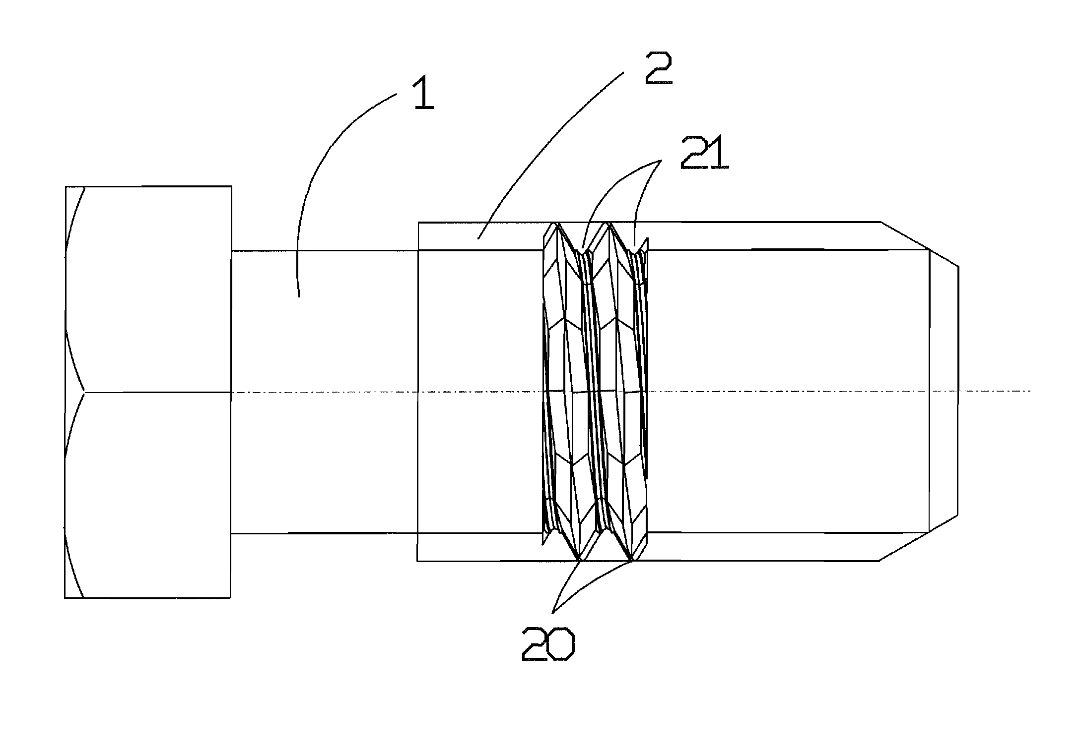
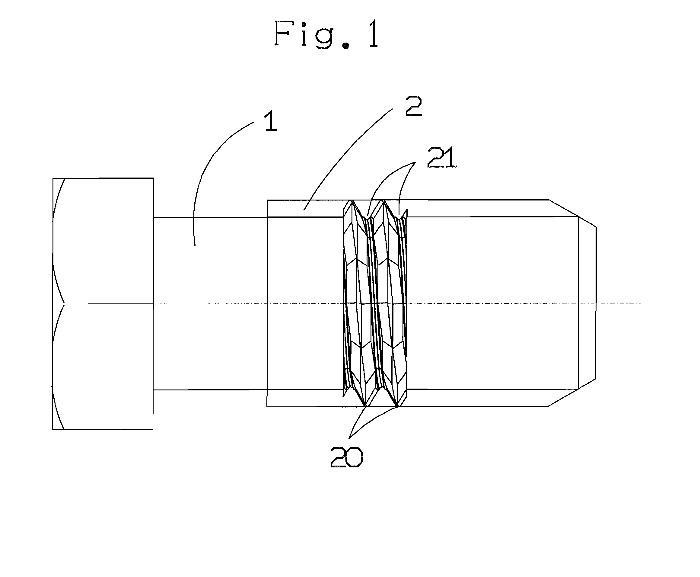
[0054] In FIG. 12, a tightening bolt 1 has multipitch threads 2. Screw threads 20 of multipitch threads 2 are linearly developed and shown in FIG. 13. FIG. 13 (A) and FIG. 13 (B1) are views of a same cut end, but are different in a sectional position and a viewing angle. On the other hand, FIG. 13 (B1) and FIG. 13 (B2) are same views, but the moving area by plastic proc...


PUM

PropertyMeasurementUnit
Forceaaaaaaaaaa
Angleaaaaaaaaaa
Heightaaaaaaaaaa

Abstract

To present a method of manufacturing a multipitch screw easily by using flat dies suited to mass production. A flat die 4 includes linear ordinary screw threads 40a, and multipitch screw threads 40b consecutive to the ordinary screw threads 40a, slightly shorter in height than the ordinary screw threads 40a, with both side walls formed alternately and consecutively, alternating between a section departing from the central line 40c of screw threads and an approaching section along a central line 40c, and symmetrically to the central line 40c of screw threads. After forming the tacks of a constant lead angle screw on the outer circumference of a shaft-like blank piece by the ordinary screw threads 40a, tracks of a multipitch screw are formed by the multipitch screw threads 40b, and therefore the tracks of a multipitch screw varying in the force applied at the time of rolling can be formed easily.

Description

TECHNICAL FIELD [0001] The invention relates to a multipitch screw having a plurality of leads (multipitch screw having screw threads formed alternately and consecutively by alternating between a lead angle obtuse section and a lead angle acute section while rotating one revolution along a helix), and a manufacturing method and a manufacturing apparatus of the same. BACKGROUND ART [0002] Numerous countermeasures have been proposed against loosening of tightening screws, but nothing has been sufficiently. [0003] The inventors have confirmed that the problem can be solved by a “multipitch screw” having a plurality of leads, that is, consecutive leads varied in pitch, which has drastically changed the conventional concept of a screw “having a spiral of a fixed pitch” (non-patent document 1). [0004] The inventors have also proposed the structure and combinations of bolts and nuts of a multipitch screw having a plurality of leads, and their application in a feed screw mechanism in JP 200...

Claims


Application Information

Patent Timeline
IPC IPC(8): B23P17/00F16B35/00
CPCB21H3/06Y10T29/54Y10T29/49F16B33/02
Inventor FUJII, HIROSHISASE, NAOKIKATAYAMA, KENICHIMORIGUCHI, YOSHINORI
Owner NAGOYA INDUSTRIAL SCIENCE RESEARCH INST
Learn More