
Connector

Inactive Publication Date: 2007-11-15
JAPAN AVIATION ELECTRONICS IND LTD
View PDF4 Cites 2 Cited by
  • Summary
  • Abstract
  • Description
  • Claims
  • Application Information

AI Technical Summary

Benefits of technology

[0015]The present invention has been made in view of these circumstances, and an object thereof is to provide a connector which enables effective use of space on a circuit board, and facilitates impedance matching between contacts.
[0018]Further, the first contacts for electrically connecting the first terminal section of the one card-type electronic device to the circuit board are held by the first housing, and the second contacts for electrically connecting the second terminal section of the other card-type electronic device to the circuit board are held by the second housing. Therefore, the first contacts and the second contacts are spaced from each other. This facilitates impedance matching between the first and second contacts.
[0019]Thus, the present invention enables the effective use of the space on the circuit board and facilitates impedance matching between the contacts.

Problems solved by technology

This makes it difficult to perform impedance matching between the electrically conductive terminals arranged in the upper housing and the electrically conductive terminals arranged in the lower housing.

Method used


Image

  • Connector
  • Connector
  • Connector

Examples


first embodiment

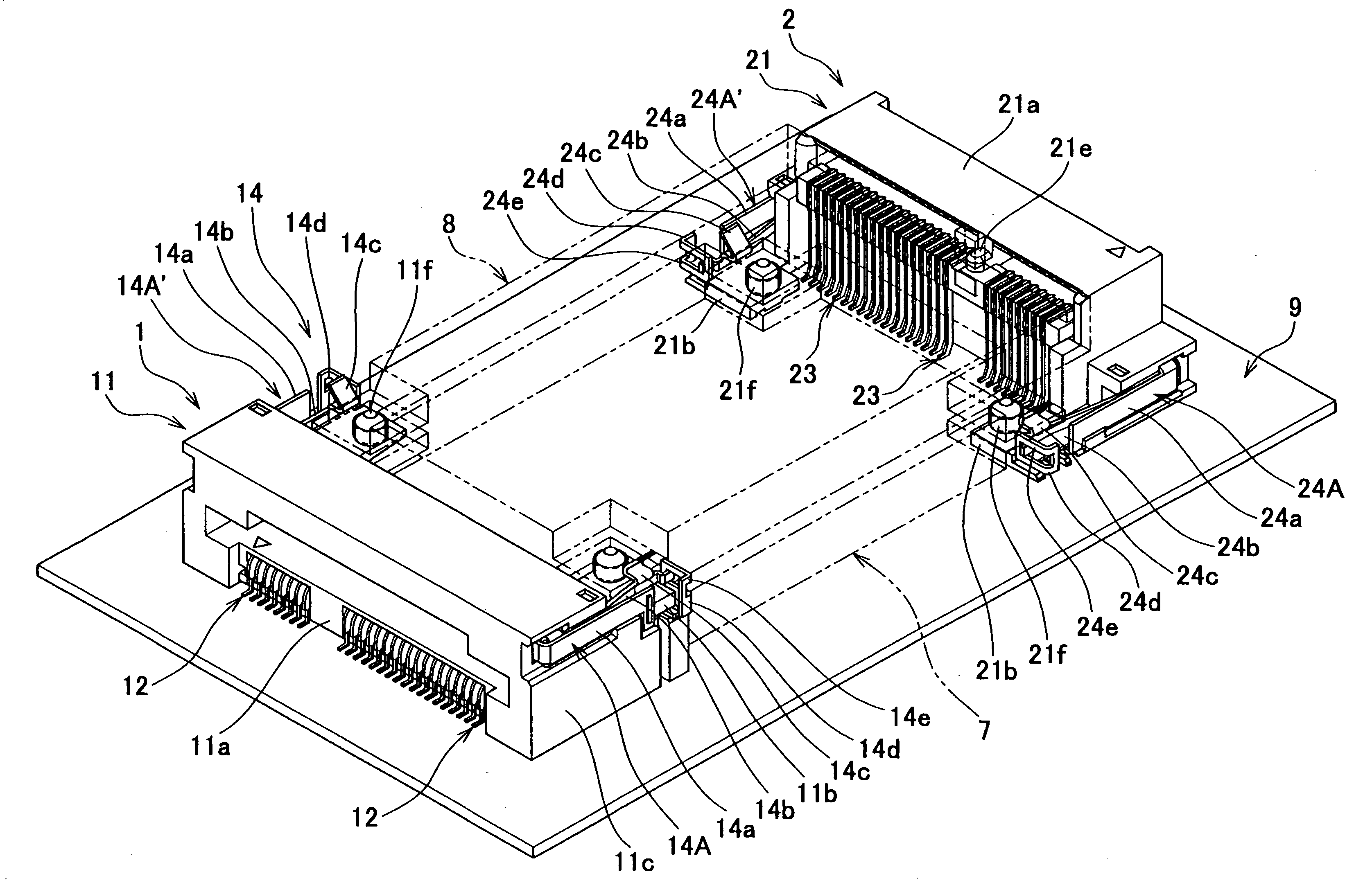
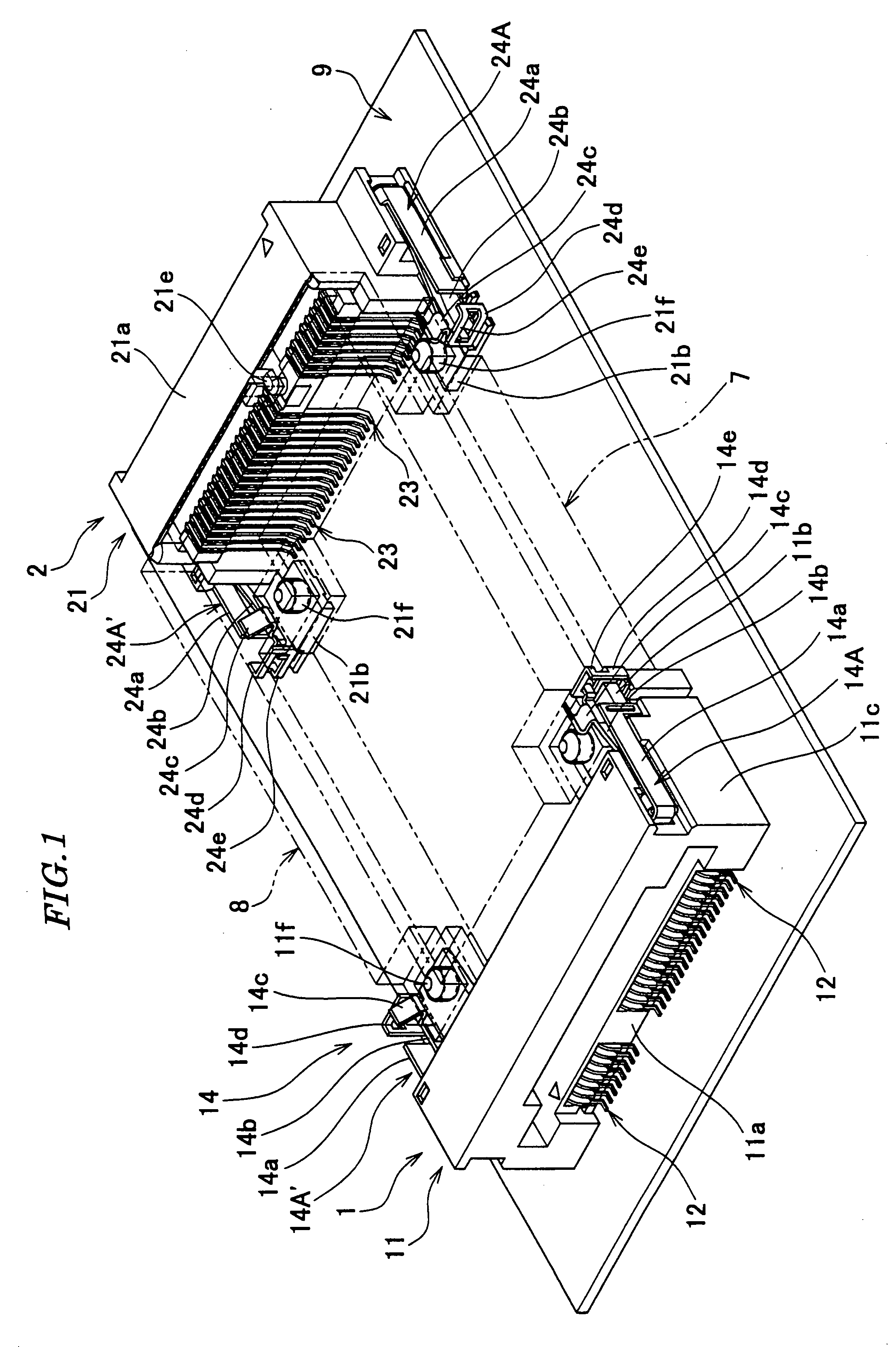
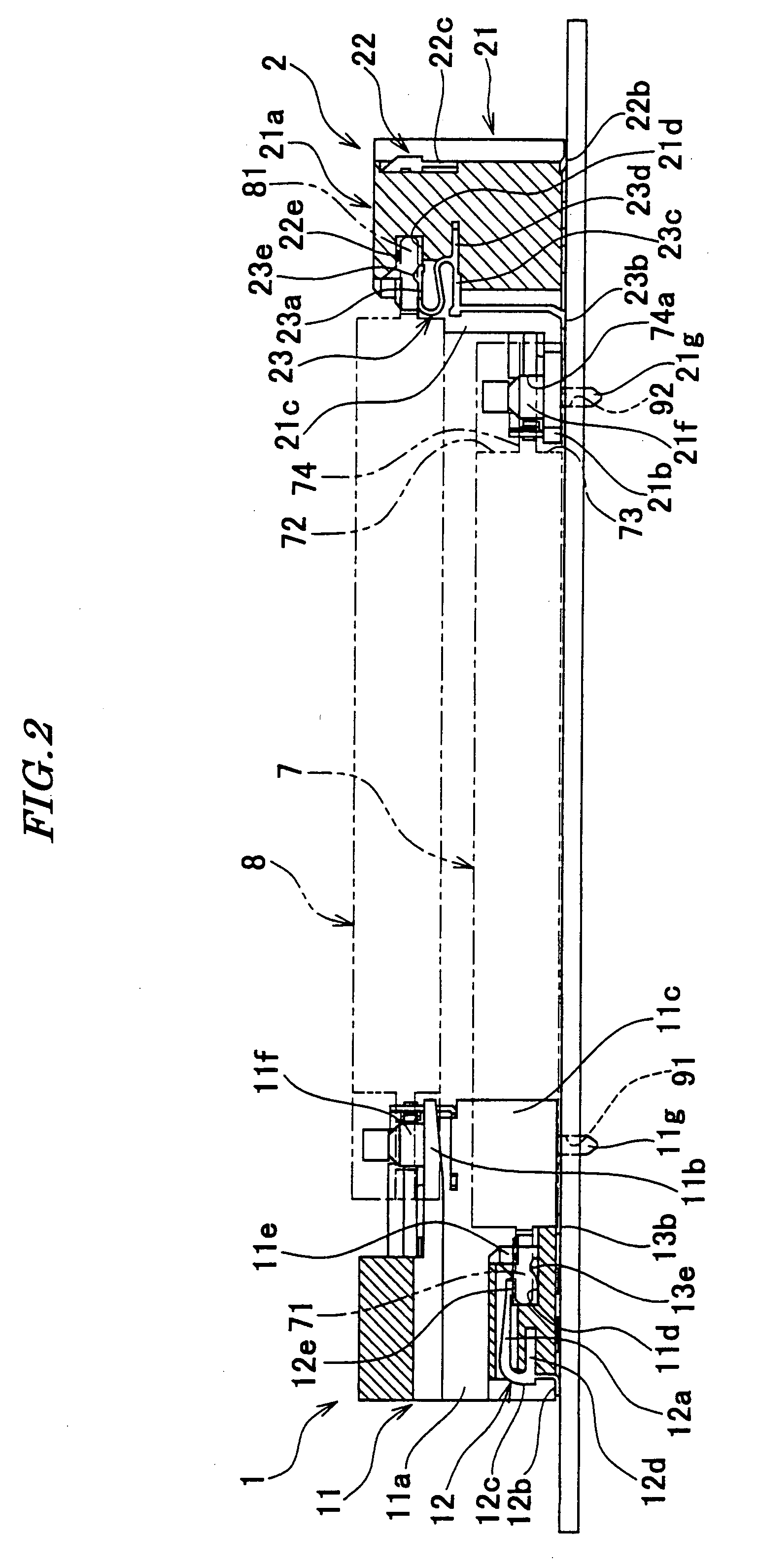
[0043]FIG. 1 is a perspective view of a card connector according to the present invention, in a state loaded with first and second function expansion cards. FIG. 2 is a cross-sectional view of the card connector in the same state as shown in FIG. 1. FIG. 3 is a plan view of the FIG. 1 card connector. FIG. 4 is a perspective view of a first connector section of the FIG. 1 card connector. FIG. 5 is a perspective view of part of a second connector section of the FIG. 1 card connector. FIG. 6 is a perspective view of a card connector in a state in which the front end of the first function expansion card is inserted into the first connector section appearing in FIG. 1. FIG. 7 is a cross-sectional view of the card connector in the same state as shown in FIG. 6. FIG. 8 is a perspective view of the card connector in a state in which a rear end of the first function expansion card is held by the second connector section of the card connector in FIG. 1. FIG. 9 is a cross-sectional view of the...

second embodiment

[0088]Referring to FIG. 12, in the connector the first connector section is provided with the ground plate (plate) 31. When the first and second function expansion cards 7 and 8 are electrically connected to the printed wiring board 9 by the first and second connector sections 1 and 2, the ground plate 31 exist between the first function expansion card 7 and the second function expansion card 8.

[0089]The ground plate 31 is an electrically conductive metal plate. The area of the ground plate 31 is substantially equal to those of the first and second function expansion cards 7 and 8. The ground plate 31 has one end thereof formed with a pair of hollow cylindrical shaft-holding portions 31a. A shaft32 is inserted through the pair of hollow cylindrical shaft-holding portions 31a, for being held by the same. Further, the one end of the ground plate 31 is formed with cutouts 31b adjacent to the respective shaft-holding portions 31a. The other end of the ground plate 31 is formed with a p...


PUM


Abstract

A connector which enables effective use of the space on a circuit board effectively, and facilitates impedance matching between contacts. The connector is comprised of a first connector section (1) and a second connector section (2). A receiving hole (11d) is formed in a first housing (11) of the first connector section (1), for receiving and holding a terminal section (71) of a first function expansion card (7). A plurality of contacts (12, 13) are arranged in the first housing (11), for electrically connecting the first function expansion card (7) to a printed wiring board (9). A first locking device (14) is disposed in the first housing (11), for locking a rear end of a second function expansion card (8). A receiving hole (21d) is formed in a second housing (21) of the second connector section (2), for receiving and holding a terminal section (81) of the second function expansion card (8). A plurality of contacts (22, 23) are arranged in the second housing (21), for electrically connecting the second function expansion card (8) to the printed wiring board (9). A second locking device (24) is disposed in the second housing (21), for locking a rear end of the first function expansion card (7).

Description

BACKGROUND OF THE INVENTION[0001]1. Field of the Invention[0002]This invention relates to a connector for electrically connecting a plurality of card-type electronic devices to a printed circuit board.[0003]2. Prior Art[0004]Conventionally, there has been proposed a card connector provided with two housings and a plurality of electrically conductive terminals (see Publication of Japanese Utility Model Registration No. 3027049 (Paragraph numbers [0010], [0012], and [0014]).[0005]The two housings are formed separately from each other, but have the same shape. Each housing is comprised of a base portion, and side portions continuously extending from opposite ends of the base portion at right angles to the base portion. Each housing is U-shaped in plan view. The two housings are stacked one upon another in a manner directed in the same direction, and are formed with an over-molded portion such that they are formed as a unitary member.[0006]A latch piece is integrally formed with a forem...

Claims


Application Information

Patent Timeline
IPC IPC(8): H01R24/00
CPCH01R13/6471H01R13/6589H01R13/6477H01R12/71
Inventor YAHIRO, YASUFUMIKATO, NOBUKAZUTAMADA, TOMOHIKO
Owner JAPAN AVIATION ELECTRONICS IND LTD
Learn More