Automatic Imaging Method and Apparatus

a technology of automatic imaging and imaging apparatus, which is applied in the direction of closed circuit television system, picture signal generator, television system, etc., can solve the problem of unsuitable tracking video image obtained

Inactive Publication Date: 2007-11-22
CHUO DENSHI
View PDF11 Cites 106 Cited by
  • Summary
  • Abstract
  • Description
  • Claims
  • Application Information

AI Technical Summary

Benefits of technology

[0009] A further object of the present invention is to enable tracking and imaging to be performed in accordance with a situation by making it possible to preset selection rules and appropriately reflect the selection operation in accordance with the importance in meaning of the imaging object.

Problems solved by technology

Therefore, when tracking and imaging one person under imaging conditions in which a plurality of persons are detected in video images that are input from the first imaging means, using only the automatic imaging method according to the prior art has not been possible to extract the position and size of the single person that is to be actually imaged in the video images, and thus suitable tracking video images could not be obtained.

Method used


Image

  • Automatic Imaging Method and Apparatus
  • Automatic Imaging Method and Apparatus
  • Automatic Imaging Method and Apparatus

Examples


embodiment 1

[0081]FIG. 3 and FIG. 4 are views that describe an automatic imaging method and automatic imaging apparatus according to a first embodiment of this invention.

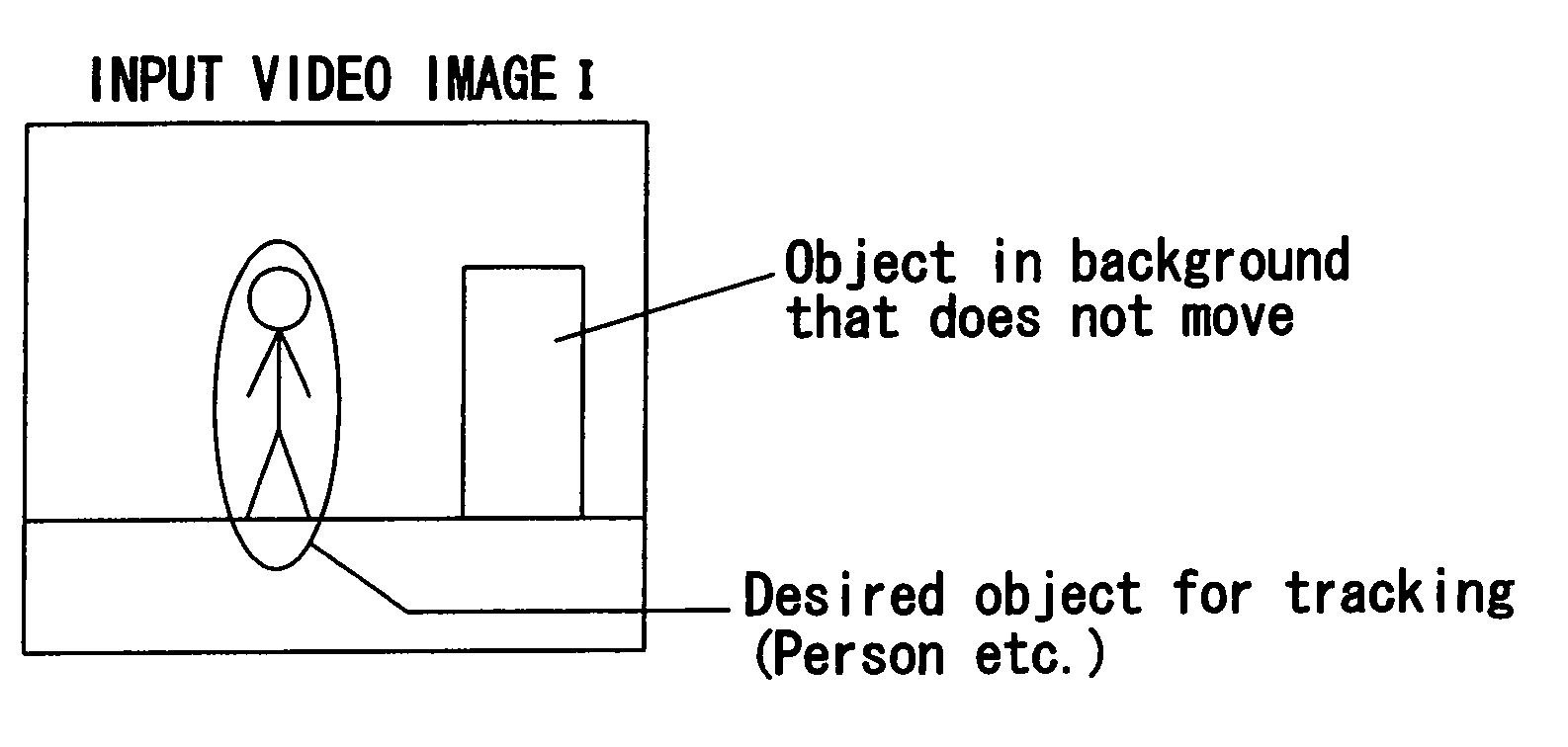
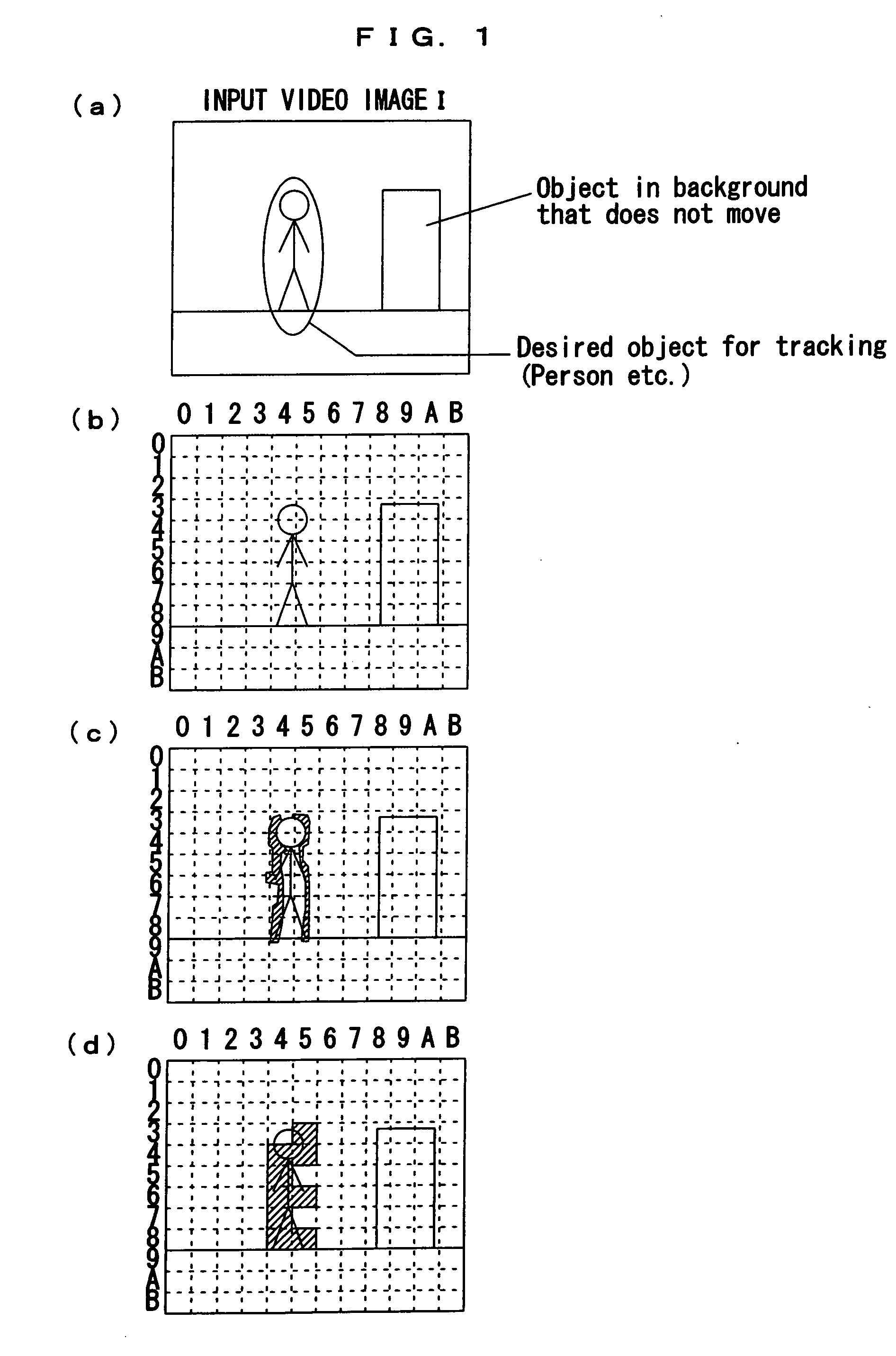
[0082] In this embodiment, in a case where a plurality of connecting regions (hereunder, referred to as “patterns”) are extracted as pattern extraction results P (set of blocks P) when patterns were extracted from an input video image I acquired from the first imaging means 1, one pattern is selected as an imaging object from among the pattern extraction results P and imaged with the second imaging means 2.

[0083] That is, in a situation in which a plurality of significant patterns (target candidates) are present simultaneously within a region (entire monitoring region) imaged by the first imaging means 1 that comprises a wide angle camera, one candidate among the plurality of target candidates present within the monitoring region is automatically selected as a target, tracking and imaging is carried out for the target with th...

embodiment 2

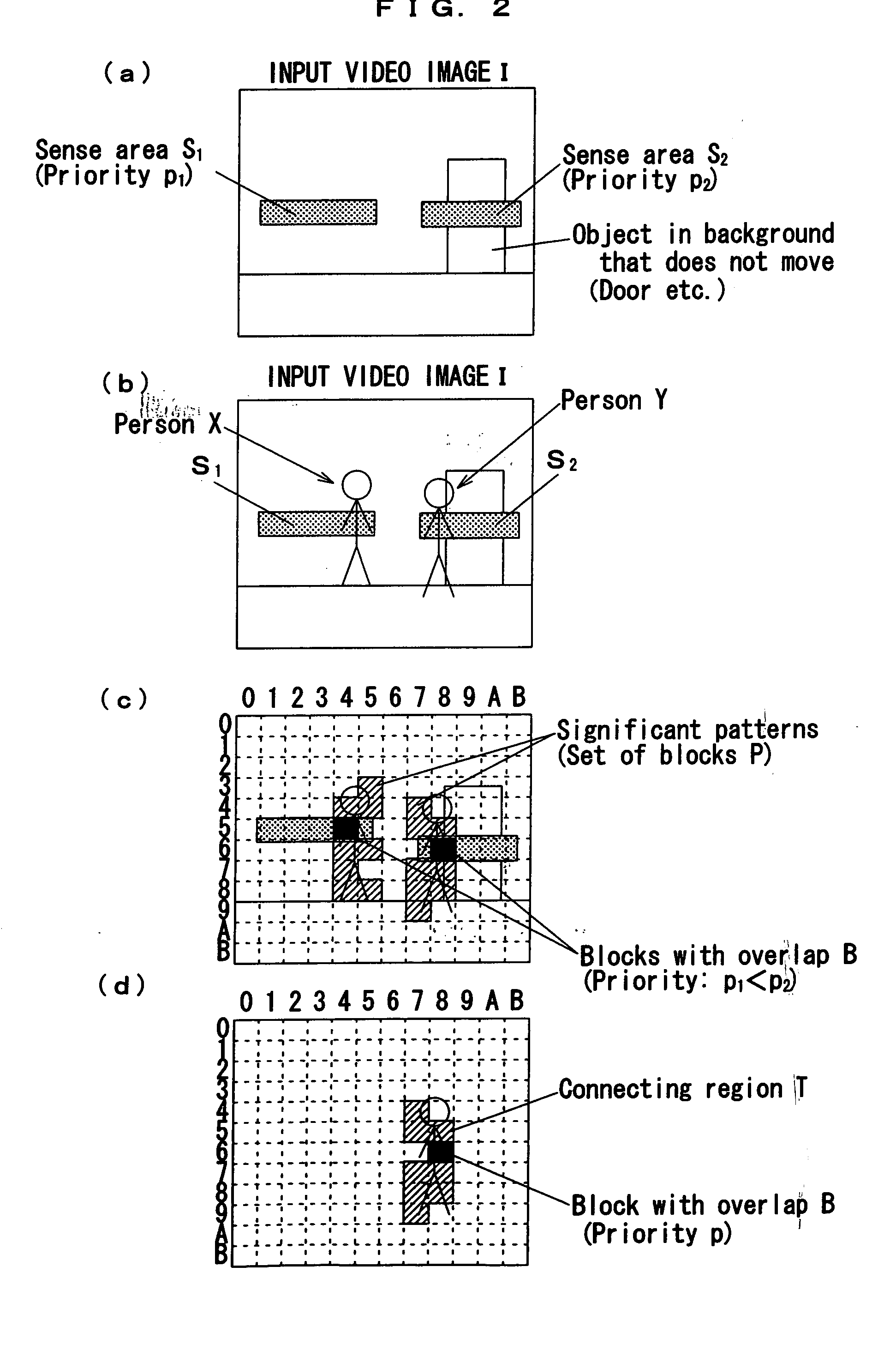
[0121] Next, an automatic imaging method and automatic imaging apparatus according to a second embodiment will be described with reference to FIG. 5 and FIGS. 6 to 10.

[0122] The automatic imaging method according to the second embodiment is a method that automatically selects a single target using the correlation between pattern extraction results and sense areas in a situation in which a plurality of significant patterns (target candidates) are simultaneously present in a region (entire monitoring region) imaged with first imaging means 1 comprising a wide angle camera, and acquires tracking video images of that target by performing tracking and imaging of the target with second imaging means 2 comprising pan, tilt and zoom functions, wherein means is provided for continuing tracking and imaging of the target that is being imaged by the second imaging means 2 even if the target moves outside a sense area.

[0123] Further, as shown in FIG. 5, the automatic imaging apparatus accordin...

embodiment 3

[0184] According to the third embodiment of this invention, a method is provided whereby, in addition to the automatic imaging method according to Embodiment 1, when a specific area among previously set sense areas is set as a sense area for entry position imaging (area E) and a target candidate having a common portion with the sense area for entry position imaging (area E) is determined as the target, the second imaging means 2 is rotated to capture the sense area for entry position imaging in which the target is present within the range of the imaging region of the second imaging means 2, and during a period in which the target is present within the sense area for entry position imaging and a pattern of a target candidate having a higher priority than the target in question is not detected, the target within the sense area for entry position imaging is imaged without changing the horizontal rotation of the second imaging means 2.

[0185] For example, with respect to the automatic i...


PUM


Abstract

An automatic imaging method is provided that selects and images one target in a monitoring environment where multiple target candidates exist on input video images. The method acquires tracking video images of a target by steps of: estimating, for each block obtained by dividing an imaging region of input video image I, whether a part or all of an object to be tracked and imaged appears in the block, and extracting set of blocks P in which the object is estimated to appear; presetting N number of regions Si (i=1, 2, 3 . . . N) of arbitrary shape on an imaging region of input video image I, together with priorities pi (i=1, 2, 3 . . . N) of each region, examining correlations between the regions Si and set of blocks P, and extracting and outputting connecting region T′ that overlaps with a region Si having highest priority among connecting regions included in the set of blocks P and overlapping with any of regions Si; and controlling second imaging means 2 to contain an object appearing in a region covered by connecting region T′ on input video image I in a field of view of second imaging means 2.

Description

TECHNICAL FIELD [0001] The present invention relates to an automatic imaging method and automatic imaging apparatus using monitoring cameras for constructing a video monitoring system. BACKGROUND ART [0002] In a video monitoring system in which video images of an entire monitoring region are captured using monitoring cameras and an operator conducts monitoring based on video images of the entire monitoring region that are displayed on a monitor, there is a large burden on the operator monitoring the images when a video image of a target that is detected within the monitoring area is displayed in a small state on a monitor. [0003] Therefore, as shown in FIG. 16, a video monitoring system has been developed that includes first imaging means comprising a wide angle camera that captures images an entire monitoring region; second imaging means comprising a camera equipped with pan, tilt, and zoom functions; and an automatic imaging apparatus main unit that detects a target based on video...

Claims


Application Information

Patent Timeline
Patent Type & Authority Applications(United States)
IPC IPC(8): H04N5/225H04N5/232H04N7/18
CPCH04N7/18H04N7/185H04N7/181
Inventor AMANO, SHISAISASHIKAWA, YOSHINORITSUKIDATE, MIZUOSASHIK'AWA, HISAYO
Owner CHUO DENSHI
Why Eureka
Try Eureka