Fuel cell stack structure and fuel cell stack structure manufacturing method

a technology of fuel cell stack structure and manufacturing method, which is applied in the direction of cell components, final product manufacturing, sustainable manufacturing/processing, etc., to achieve the effect of improving output density and improving output density

Inactive Publication Date: 2007-11-22
NISSAN MOTOR CO LTD
View PDF7 Cites 18 Cited by
  • Summary
  • Abstract
  • Description
  • Claims
  • Application Information

AI Technical Summary

Benefits of technology

[0009] The present invention was conceived in view of this need. One object of the present invention is to provide a fuel cell stack structure that has an improved output density and is configured and arranged such that the solid electrolyte fuel cell units can be fastened together as they are pressurized in the stacking direction and the pressurized state can be maintained for a long period of time. It is also an object of the present invention to provide a manufacturing method for manufacturing a fuel cell stack structure that has an improved output density.

Problems solved by technology

However, since the tie rod is long, it becomes a main impediment to constructing a fuel cell stack structure having a high output density.

Method used


Image

  • Fuel cell stack structure and fuel cell stack structure manufacturing method
  • Fuel cell stack structure and fuel cell stack structure manufacturing method
  • Fuel cell stack structure and fuel cell stack structure manufacturing method

Examples


second embodiment

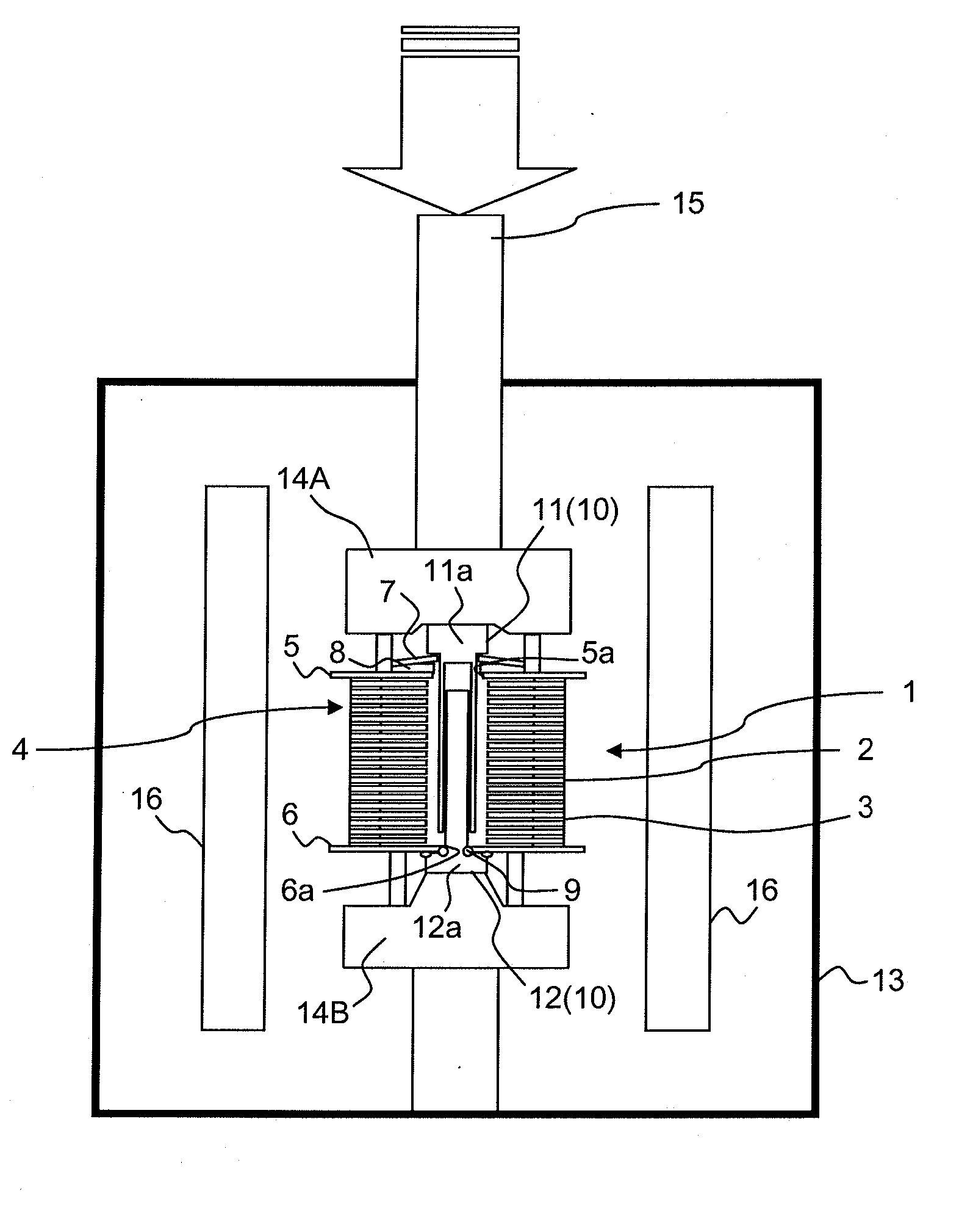
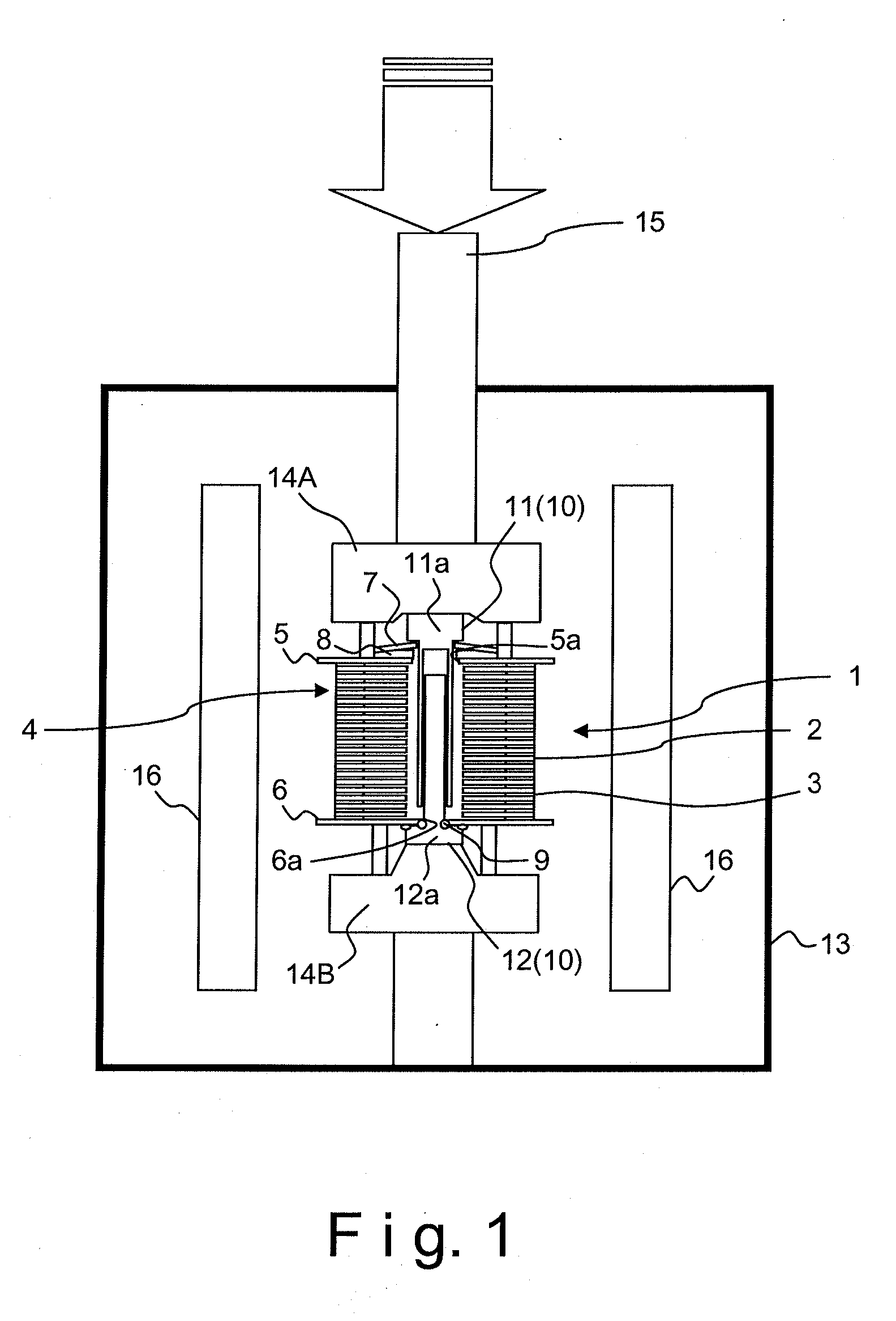
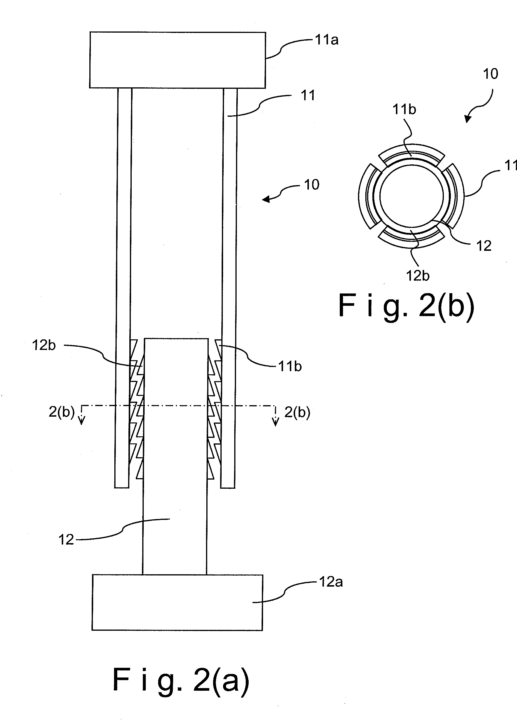
[0052] Referring now to FIGS. 5 to 8, a fuel cell stack structure 1″ in accordance with a second embodiment will now be explained. In view of the similarity between the first and second embodiments, the parts of the second embodiment that are identical to the parts of the first embodiment will be given the same reference numerals as the parts of the first embodiment. Moreover, the descriptions of the parts of the second embodiment that are identical to the parts of the first embodiment may be omitted for the sake of brevity.

[0053]FIG. 5 is a simplified vertical cross sectional view of the fuel cell stack structure 1″ in accordance with the second embodiment. The fuel cell stack structure 1″ of the second embodiment differs from the fuel cell stack structure 1 of the first embodiment in that the fuel cell stack structure 1″ of the second embodiment uses a metallic glass material (oining material) 23 as the fixing member configured and arranged to fasten an outer cylinder 21 and an i...

third embodiment

[0103] Referring now to FIGS. 12 and 13, a fuel cell stack structure in accordance with a third embodiment will now be explained. In view of the similarity between the second and third embodiments, the parts of the third embodiment that are identical to the parts of the second embodiment will be given the same reference numerals as the parts of the second embodiment. Moreover, the descriptions of the parts of the third embodiment that are identical to the parts of the second embodiment may be omitted for the sake of brevity.

[0104] The fuel cell stack structure of the third embodiment is basically identical to the fuel cell stack structure 1″ of the second embodiment illustrated in FIG. 5 except that a tie rod 60 is used in the third embodiment instead of the tie rod 20. Thus, only the structures of the tie rod 60 will be explained in detail below.

[0105]FIG. 12 is a simplified vertical cross sectional view of the tie rod 60 in accordance with the third embodiment of the present inv...


PUM

PropertyMeasurementUnit
thicknessaaaaaaaaaa
thicknessaaaaaaaaaa
thicknessaaaaaaaaaa

Abstract

A fuel cell stack structure is basically provided with a stack entity and at least one tie rod. The stack entity includes a plurality of solid electrolyte fuel cell units stacked together in a stacking direction. The tie rod extends through the stack entity to fasten the solid electrolyte fuel cell units so that the solid electrolyte fuel cell units are pressed against each other in the stacking direction. The tie rod has an outer cylinder, an inner shaft fitting into the outer cylinder, and a fixing member that fastens the outer cylinder and the inner shaft together in an axial direction of the tie rod.

Description

CROSS-REFERENCE TO RELATED APPLICATIONS [0001] This application claims priority to Japanese Patent Application No. 2006-093522, filed on Mar. 30, 2006. The entire disclosure of Japanese Patent Application No. 2006-093522 is hereby incorporated herein by reference. BACKGROUND OF THE INVENTION [0002] 1. Field of the Invention [0003] The present invention relates to a fuel cell stack structure having a stack entity including a plurality of solid electrolyte fuel cells stacked together. [0004] 2. Background Information [0005] A conventional fuel cell stack structure includes, for example, a stack entity having a plurality of solid electrolyte fuel cell units and a tie rod that passes through the stack entity to secure and apply pressure to the solid electrolyte fuel cell units. The solid electrolyte fuel cell units are stacked together with a sealing material having a gas sealing capability being disposed between the solid electrolyte fuel cell units. [0006] U.S. Pat. No. 6,344,290 disc...

Claims


Application Information

Patent Timeline
Patent Type & Authority Applications(United States)
IPC IPC(8): H01M2/00
CPCH01M8/0276H01M8/028H01M8/0282Y02E60/50H01M8/241H01M8/248H01M8/10Y02P70/50H01M8/0258H01M8/0271H01M8/0297H01M8/2425
Inventor NAKAJIMA, YASUSHIYAGUCHI, TATSUYASAKAMOTO, HIROKIOWADA, YUSAKURAI, HIROSHIYASUDA, YOSHITERU
Owner NISSAN MOTOR CO LTD
Why Eureka
Try Eureka