
Moving length adjustment device of a treading trainer

a technology of adjusting device and trainer, which is applied in the field of treadmills, can solve the problems of inability to use, inconvenient operation, and danger, and achieve the effect of reducing the weight of the treading trainer and reducing the cos

Inactive Publication Date: 2007-11-22
LIN KUAN I
View PDF8 Cites 29 Cited by
  • Summary
  • Abstract
  • Description
  • Claims
  • Application Information

AI Technical Summary

Benefits of technology

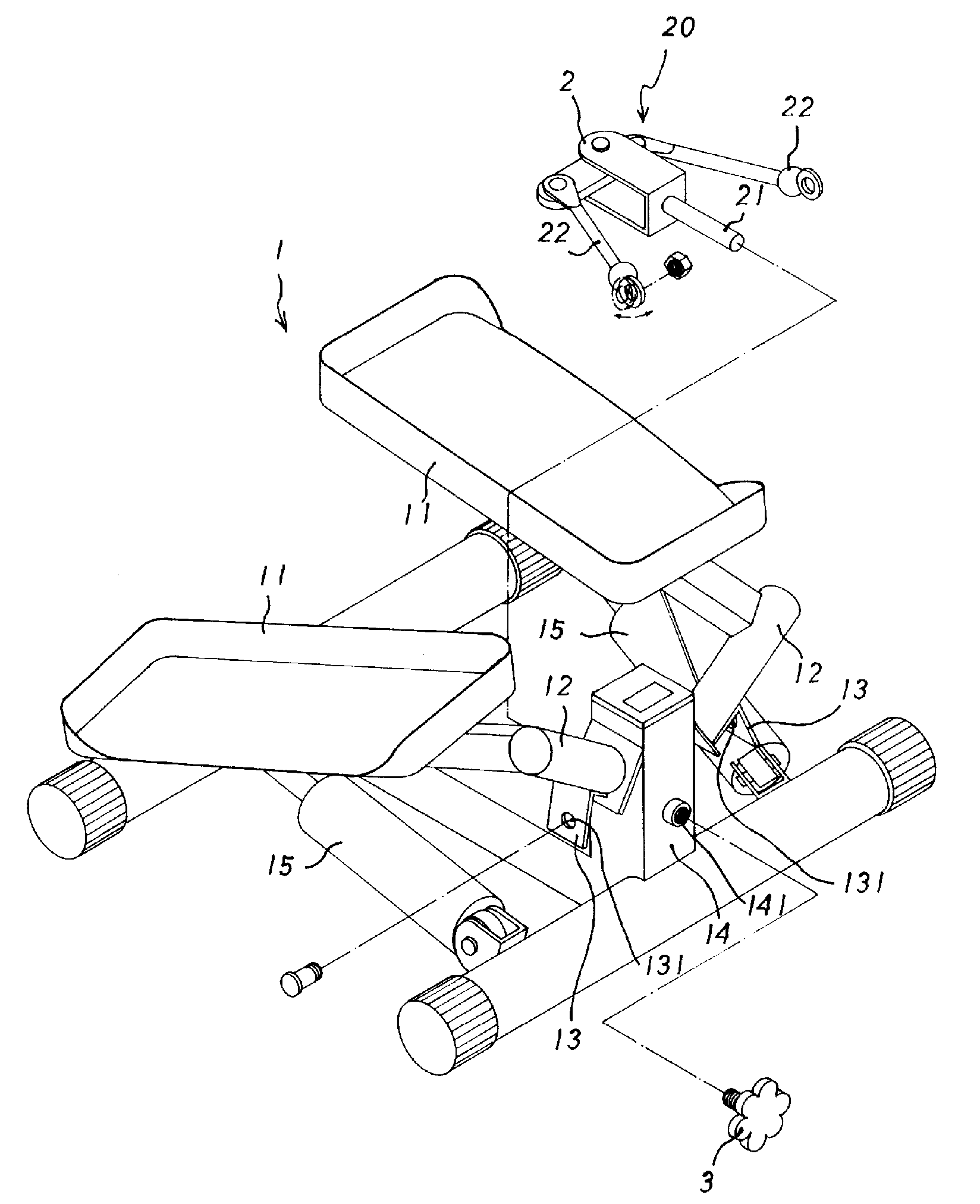
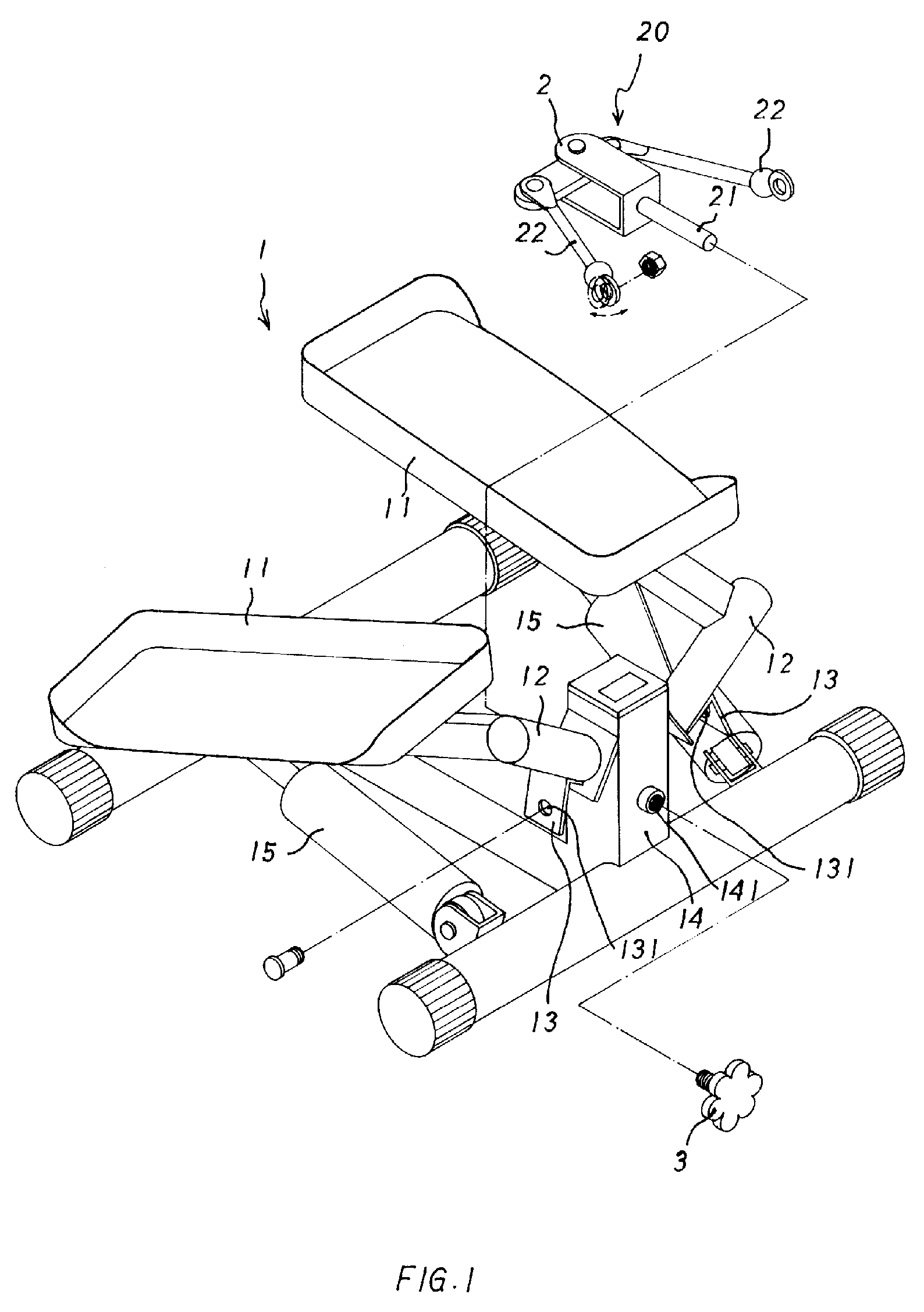
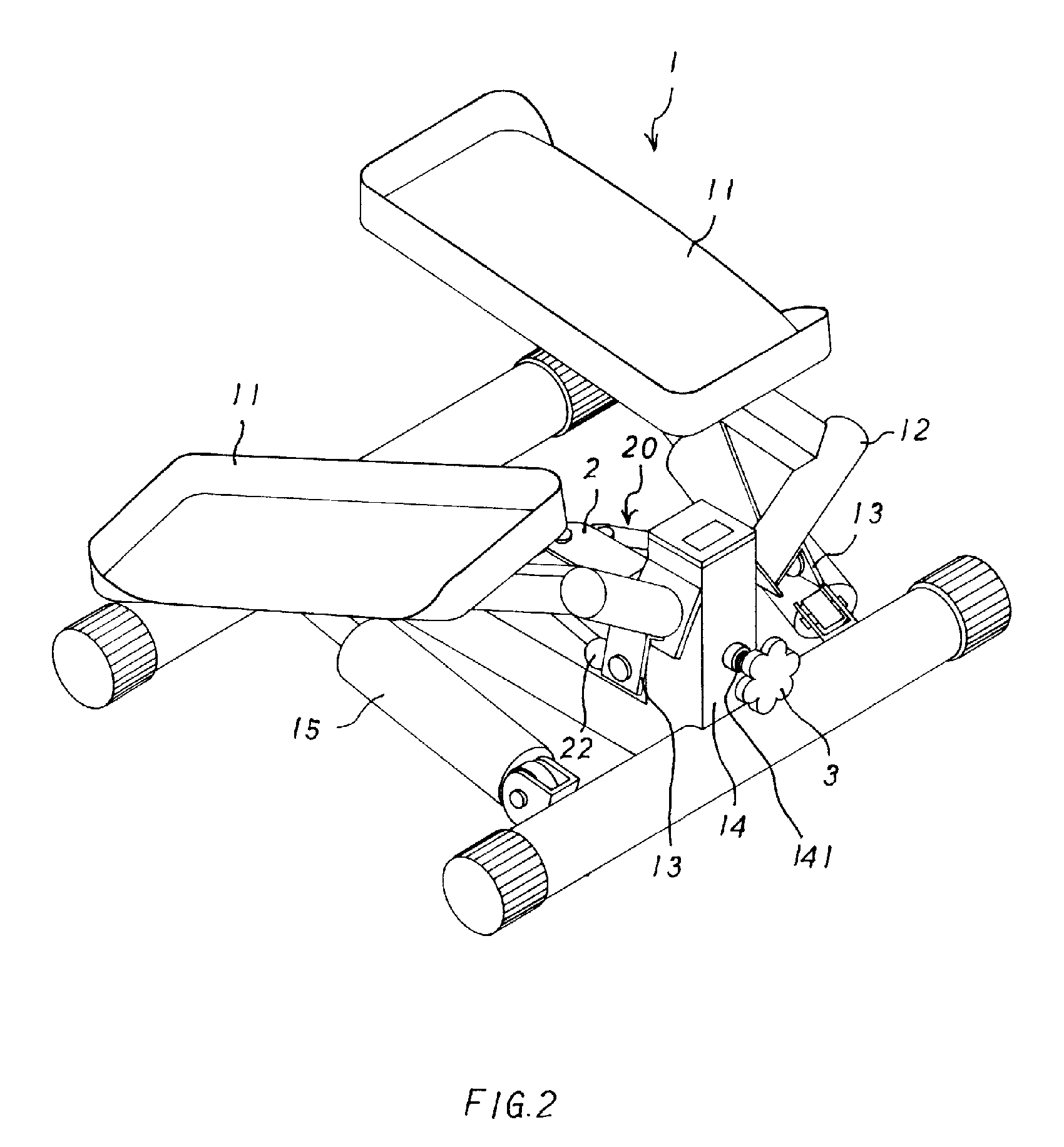
[0004]Accordingly, the primary object of the present invention is to provide a moving length adjustment device of a treading trainer, wherein a T shape linkage has universal adaptors at two sides thereof. The universal adaptors will insert into the linkage plates so as to be connected to the treadles. A pin shaft of the T shape linkage is inserted into a screw hole of a stand rod and a screw rod also inserted into the screw hole from another end of the screw hole. By adjustment of the screw rod, the swing angles of the T shape linkage can displace forwards or backwards so that the moving length of the treadles are adjusted. Thus, the cost is reduced and the weight of the treading trainer is decreased. The convenience of the treading trainer is retained without effect by the installation of the moving length adjustment device.
[0005]Furthermore, in the present invention, the T shape linkage has the effect of reducing the shift form the movement of the treadles by the swinging operation of the T shape linkage. Thus no deform occurs.

Problems solved by technology

Thus, it is often that the moving length of the treadle is not suitable for everyone and therefore, the moving length of the treadle is necessary to be adjusted.
However the prior art treading trainer has no such design and thus users must match the steps themselves to the treadles or the treading forces and length must be controlled so as to have a desire moving length.
Not only the operation is inconvenient and some dangers exist.
As a result the uses are not willing to use it.

Method used


Image

  • Moving length adjustment device of a treading trainer
  • Moving length adjustment device of a treading trainer
  • Moving length adjustment device of a treading trainer

Examples


Embodiment Construction

[0016]In order that those skilled in the art can further understand the present invention, a description will be provided in the following in details. However, these descriptions and the appended drawings are only used to cause those skilled in the art to understand the objects, features, and characteristics of the present invention, but not to be used to confine the scope and spirit of the present invention defined in the appended claims.

[0017]Referring to FIG. 1, the moving length adjustment device of a treading trainer according to the present invention is illustrated. The present invention has the following elements.

[0018]A treading trainer 1 has two treadles 11. Each treadle 11 is indirectly connected to a rotary shaft 12. The rotary shaft 12 is connected to a linkage plate 13. The linkage plate 13 is formed with a via hole 131. Each linkage plate 13 is indirectly connected to a stand rod 14. The stand rod 14 is formed with a transversal screw hole 141. A driving cylinder 15 (a...


PUM


Abstract

A moving length adjustment device of a treading trainer comprises a treading trainer having two treadles; each treadle indirectly connected to a rotary shaft; the rotary shaft connected to a linkage plate; each linkage plate being formed with a via hole; each linkage plate being indirectly connected to a stand rod; the stand rod being formed with a transversal screw hole; and a T shape linkage having a pin shaft at a front end thereof; each of two lateral sides of the T shape linkage having a respective universal adaptor. Further, the T shape linkage can be replaced by a retaining frame, a guide wheel and a steel rope winding around the guide wheel; and a front end of the steel rope having a pin shaft.

Description

FIELD OF THE INVENTION[0001]The present invention relates to treading trainers, and in particular to a moving length adjustment device of a treading trainer, wherein a T shape linkage has universal adaptors at two sides thereof. The universal adaptors will insert into the linkage plates so as to be connected to the treadles. A pin shaft of the T shape linkage is inserted into a screw hole of a stand rod and a screw rod is also inserted into the screw hole from another end of the screw hole. By adjustment of the screw rod, the swing angles of the T shape linkage can displace forwards or backwards so that the moving length of the treadles are adjusted.BACKGROUND OF THE INVENTION[0002]Treading trainers are simple and convenient body training machines. Users feel comfortable in using the machine. By the movement of the treadles, the user can get the affect of walking indoors.[0003]However everyone has different steps. Thus, it is often that the moving length of the treadle is not suitab...

Claims


Application Information

Patent Timeline
IPC IPC(8): A63B22/04
CPCA63B21/0083A63B21/0087A63B2022/0074A63B23/0429A63B22/0069
Inventor LIN, KUAN-I
Owner LIN KUAN I
Learn More