Wireless Electrode for Biopotential Measurement

a biopotential voltage and wireless technology, applied in the field of wireless electrodes for biopotential voltage measurement, can solve the problems of long electrode wires, affecting the accuracy of measurements, affecting the utility of the system, etc., and achieve the effect of improving signal detection and being simple to set up and us

Inactive Publication Date: 2007-11-22
NEURONETRIX SOLUTIONS
View PDF9 Cites 178 Cited by
  • Summary
  • Abstract
  • Description
  • Claims
  • Application Information

AI Technical Summary

Benefits of technology

[0020] The invention overcomes the above-noted and other deficiencies of the prior art by providing a wireless biopotential measuring device with improved signal detection that is simple to set up and use in a clinical environment.

Problems solved by technology

For many applications of biopotential measurement, the long electrode wires present a number of problems both in terms of the utility of the system and the accuracy of the measurements.
Affixing a multitude of individual electrodes to the patient's skin and attaching the other ends to an equipment box also requires a significant amount of time.
Not only are the long attachment wires burdensome themselves, the wires also tend to limit the accuracy of the electrophysiological signals being detected.
First, the wires act as an antenna which will pick up stray background electrical noise.
The second reason that long wires limit the accuracy of the detected signals is that because the signals are very small, on the order of millivolts (10−3 volt) or microvolts (10−6 volt), there is a certain amount of signal loss due to the impedance of the wire.
Finally, as the physicians and nurses work around the patient, the wires are often disturbed.
Disturbing the wires can create noise and cause signal degradation.
While this system and the device described in U.S. Pat. No. 6,654,626 do shorten setup time, these systems still require a cable between the electrode strip and the monitor.
This wire can get in the way of the care givers and, if disturbed, could cause the electrode strip to become detached.
The long electrode wire can also cause signal noise and degradation.
While this system amplifies a cleaner signal, the long wires between the electrode and the junction box are still problematic.
This system does not amplify the signal close to the skin contact point.
This does not eliminate the problems associated with the clutter of wires and signal degradation can occur because of the long electrode wires.
The BioRadio Jr. does include a signal amplifier, an analog to digital converter, and a radio transmitter, and is battery powered, but this system does not utilize a preformed, adhesive electrode strip.
The device, as described in their marketing literature, does not include a practical packaging arrangement.
There is also no discussion of a method to automatically identify the specific biopotential measurement taken and therefore there is no method to preset the signal gain, filtering, or data capture or transmit rate.
This device is deficient for biopotential measurements for several reasons.
First, the sensors are packaged close together and do not provide enough separation between the signal and reference electrodes to get an accurate measurement of voltage potential.
The device also does not include an identification chip to facilitate automatic system configuration.
While this system does eliminate this wired connection, other issues of usability are not addressed.

Method used


Image

  • Wireless Electrode for Biopotential Measurement
  • Wireless Electrode for Biopotential Measurement
  • Wireless Electrode for Biopotential Measurement

Examples


Embodiment Construction

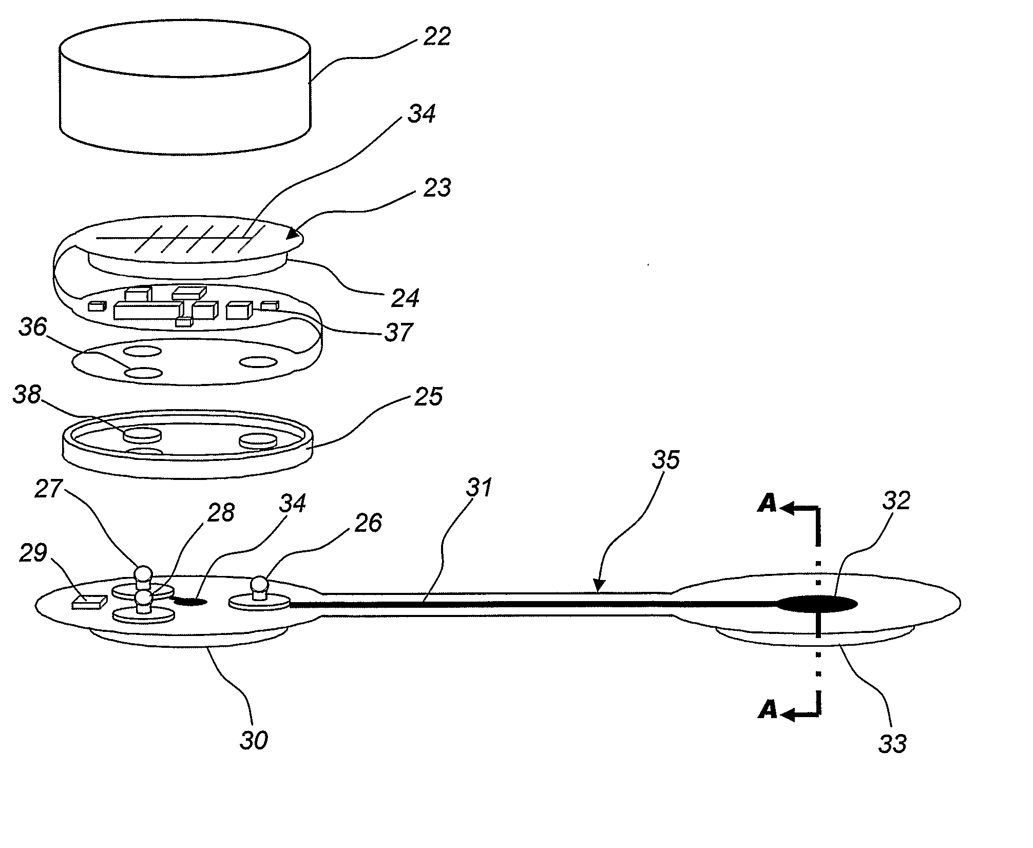
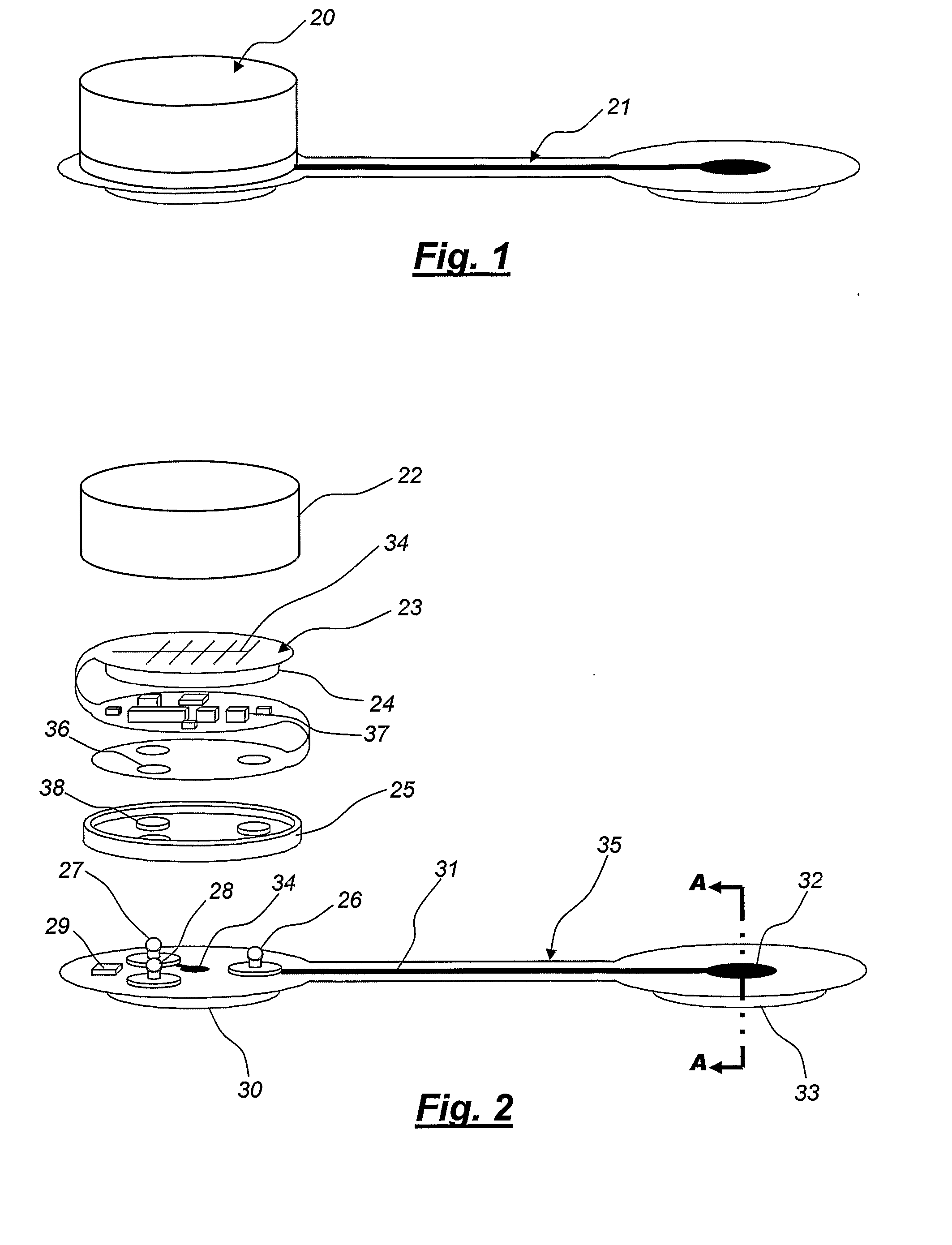
[0036] A sealed electronics module is described which encloses a flexible printed circuit with various integrated circuit devices attached. These integrated circuits include amplifiers, analog to digital converters, a microcontroller, random access memory, and a digital radio. Also included in the module are a battery and an antenna integrated onto the flexible circuit.

[0037] The invention also includes a flexible electrode strip with at least one electrode contact affixed to each end. A memory chip containing a digital identifier is affixed to the electrode strip. Contact plugs are affixed to the electrode strip and are electrically connected to electrode pads and to the identifier memory chip.

[0038] The electrode strip has an adhesive backing so that it can be adhesively affixed to a location on a subject's skin, such as the forehead. The electrode contacts may be impregnated with an electrolytic substance to enhance the skin conductance. Once the electronics module is attached ...


PUM


Abstract

A wireless biopotential monitoring system composed of a wireless electrode module which can be attached to a disposable electrode strip. Such device can be conveniently affixed to a patient's skin and will transmit the physiological signals to a remote receiver where the signals can be monitored by a clinician.

Description

CROSS REFERENCE TO RELATED APPLICATIONS [0001] The present application claims the benefit of U.S. patent application Ser. No. 60 / 580,776 “DEVICE AND METHOD FOR TRANSMITTING PHYSIOLOGIC DATA” and 60 / 580,772 “WIRELESS ELECTRODE FOR BIOPOTENTIAL MEASUREMENT” both to Fadem et al. and filed on 18 Jun. 2004, the disclosure of both of which are incorporated by reference in its entirety.FIELD OF THE INVENTION [0002] The present invention relates generally to a method and apparatus for capturing biopotential voltage signals such as electroencephalograms (EEG's), electrocardiograms (ECG's) or electromyograms (EMG's). More particularly, the present invention provides a method and describes a battery powered device which uses a digital amplification circuit attached to a disposable adhesive electrode strip to capture voltage potentials from the surface of the skin and a digital wireless transceiver tightly integrated with respect to the amplification circuit to send the voltage potential signal...

Claims


Application Information

Patent Timeline
Patent Type & Authority Applications(United States)
IPC IPC(8): A61B5/04A61B5/00A61B5/0205A61B5/308G08B1/08H04Q7/00
CPCA61B5/0006A61B2562/242A61B5/02055A61B5/04004A61B5/0402A61B5/04085A61B5/0428A61B5/1112A61B5/1455A61B5/68A61B5/6833A61B2560/0412A61B2503/20A61B2505/01A61B2562/166A61B5/0008A61B5/30A61B5/282A61B5/318
Inventor FADEM, KALFORD C.SCHNITZ, BENJAMIN A.
Owner NEURONETRIX SOLUTIONS
Why Eureka
Try Eureka