Vision guidance system and method for identifying the position of crop rows in a field

a technology of vision guidance and crop rows, applied in the field of guidance systems, can solve the problems of high sensitiveness of the pattern recognition methods used with conventional crop row detection techniques to noise picked up in field scene images, and achieve the effects of reducing processing burden, increasing responsiveness, and adding robustness to the system and method

Active Publication Date: 2007-11-22
FOSTER-MILLER
View PDF9 Cites 28 Cited by
  • Summary
  • Abstract
  • Description
  • Claims
  • Application Information

AI Technical Summary

Benefits of technology

[0008]This system and method of identifying a position of a crop row allows for reduced processing burden and / or increased responsiveness by constraining the search space for a preferential heading of the vehicle. In addition, normalization techniques are utilized to add robustness to the system and method while reducing the certain negative effects of inconsistent lighting and image data collection.

Problems solved by technology

In addition, the principal pattern recognition methods used with conventional crop row detection techniques are highly sensitive to noise picked up in the field scene images.

Method used


Image

  • Vision guidance system and method for identifying the position of crop rows in a field
  • Vision guidance system and method for identifying the position of crop rows in a field
  • Vision guidance system and method for identifying the position of crop rows in a field

Examples


Embodiment Construction

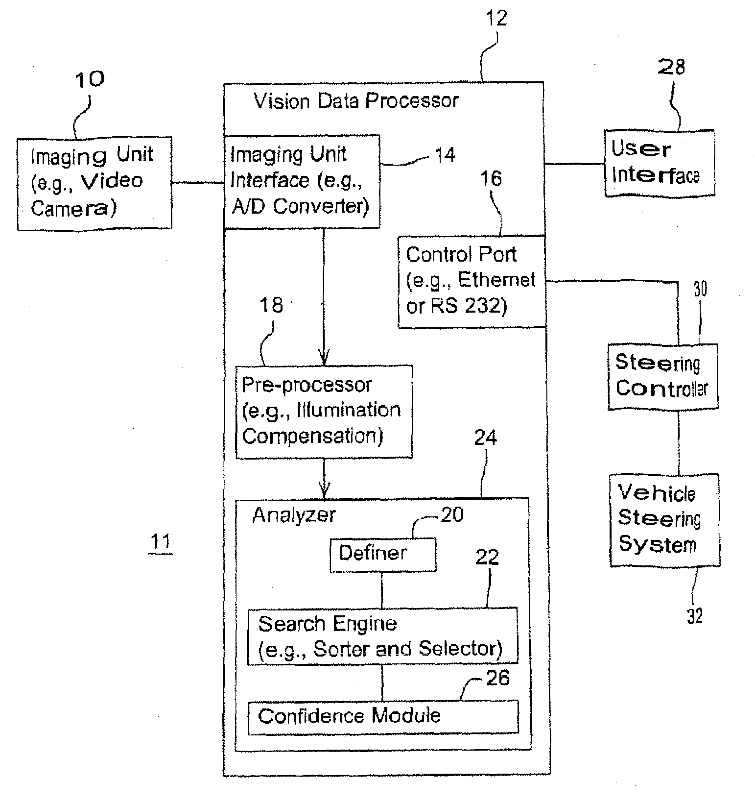
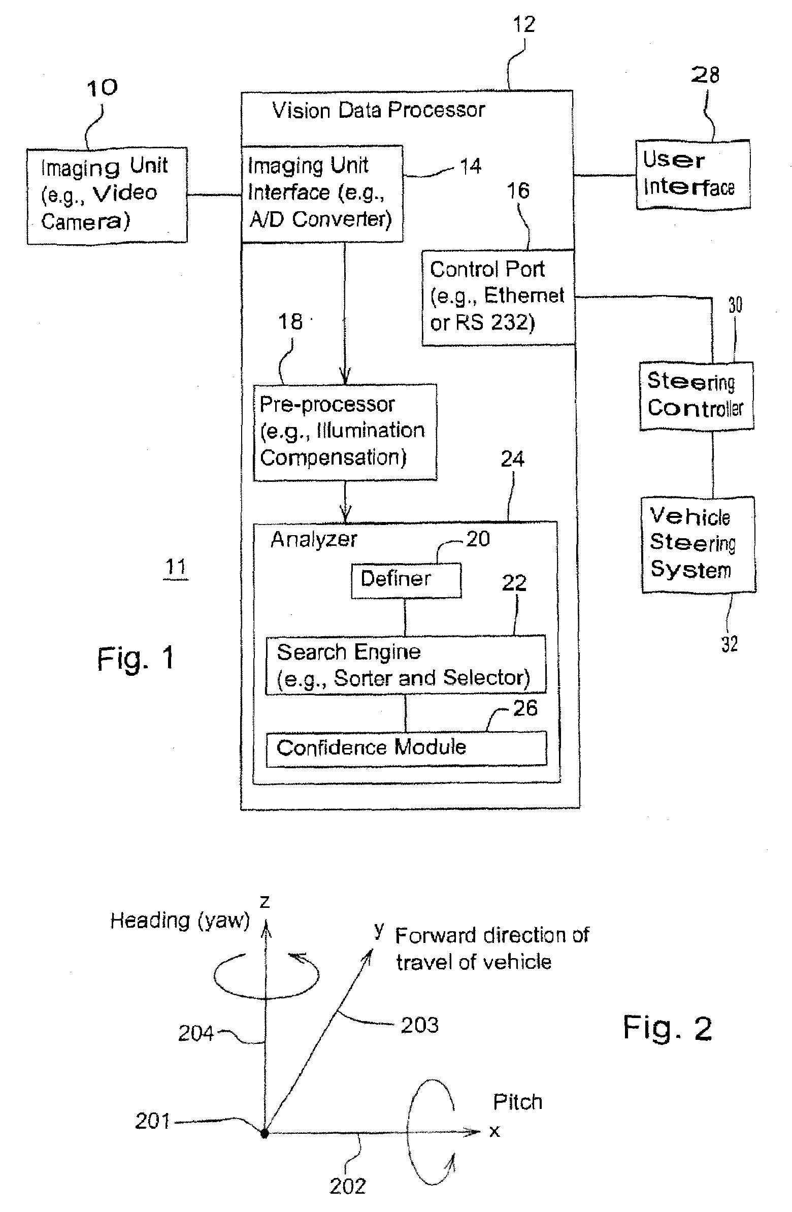
[0027]In accordance with one embodiment of the present invention, FIG. 1 illustrates a vision guidance system 11 for determining the position of rows with respect to a vehicle. The examples discussed hereafter relate to crop rows in an agricultural field. The vehicle may comprise a tractor, a combine, a harvester, a sprayer, an agricultural vehicle, or any other type of vehicle or entity requiring guidance. An imaging unit 10 (e.g., a video camera) can be directly or indirectly coupled to a vision data processor 12, where the imaging unit 10 can be mounted on a vehicle. Alternatively, the imaging unit 10 can be integrated into or with the vision data processor 12 if desired. The vision data processor 12 may comprise an imaging unit interface 14 (e.g., an analog to digital converter), a pre-processor 18, a control port 16 (e.g., Ethernet, RS 232, etc.), an analyzer 24, and at least one memory unit (not shown). The vision data processor 12 may also be associated with a user interface ...


PUM


Abstract

A system and method of identifying a position of a crop row in a field, where an image of two or more crop rows is transmitted to a vision data processor. A preferential scan line profile in a search space about a candidate scan line profile is determined, and the candidate scan line profile is identified as a preferential scan line profile for estimating a position (e.g., peak variation) of one or more crop rows if a variation in the intensity level of the candidate scan line profile exceeds a threshold variation value. Alternatively, a position datum associated with a highest intensity value within the array of vector quantities can be selected as being indicative of a candidate position of a crop row. The candidate position is then identified as a preliminary row position if a variation in intensity level of the candidate scan line profile exceeds a threshold variation value.

Description

CROSS-REFERENCE TO RELATED PATENT APPLICATIONS[0001]This application claims priority from U.S. Provisional Application 60 / 801,456, filed May 18, 2006, incorporated herein by reference in its entirety.FIELD OF THE INVENTION[0002]The present invention relates generally to guidance systems. In particular, the present invention relates to vision guidance systems for identifying the position of crop rows in a field with respect to a vehicle.BACKGROUND OF THE INVENTION[0003]This section is intended to provide a background or context to the invention that is recited in the claims. The description herein may include concepts that could be pursued, but are not necessarily ones that have been previously conceived or pursued. Therefore, unless otherwise indicated herein, what is described in this section is not prior art to the description and claims in this application and is not admitted to be prior art by inclusion in this section.[0004]Vision systems may use one or more imaging units such ...

Claims


Application Information

Patent Timeline
Patent Type & Authority Applications(United States)
IPC IPC(8): G01C21/30
CPCG01C11/00A01B69/001
Inventor JOCHEM, TODDBATAVIA, PARAGOLLIS, MARK
Owner FOSTER-MILLER
Why Eureka
Try Eureka