
Method and apparatus using a dual axis optical dithering system to increase a perceived resolution of a display

a dual-axis optical dithering and display technology, applied in the field of display systems, can solve the problems of requiring a relatively small amount of space in the projection path and the configuration of the optical dithering system may have a low number of parts, so as to increase the perceived resolution of the display and increase the display. the effect of resolution

Inactive Publication Date: 2007-11-29
TEXAS INSTR INC
View PDF15 Cites 0 Cited by
  • Summary
  • Abstract
  • Description
  • Claims
  • Application Information

AI Technical Summary

Benefits of technology

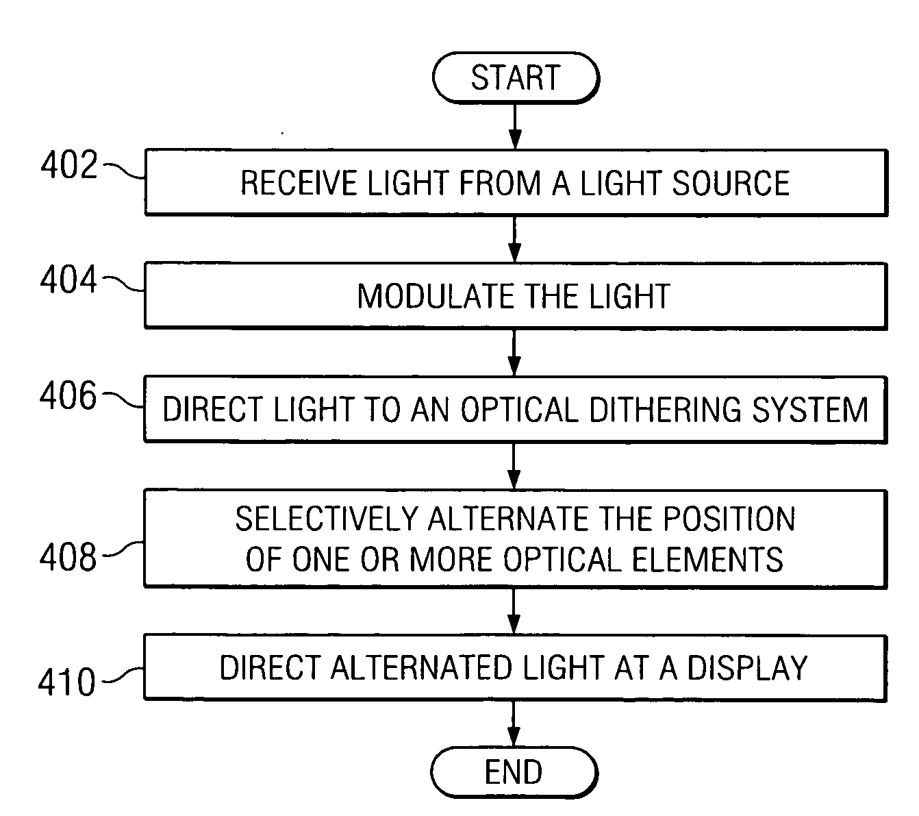
[0004]According to one embodiment, a method of increasing a perceived resolution of a display includes directing light at an optical dithering system. The position of one or more optical elements associated with the optical dithering system is selectively alternated between a first set of positions relative to a first axis of rotation and a second set of positions relative to a second axis of rotation. As a result, light is alternately directed to at least four different locations on the display, thereby increasing the perceived resolution of the display.
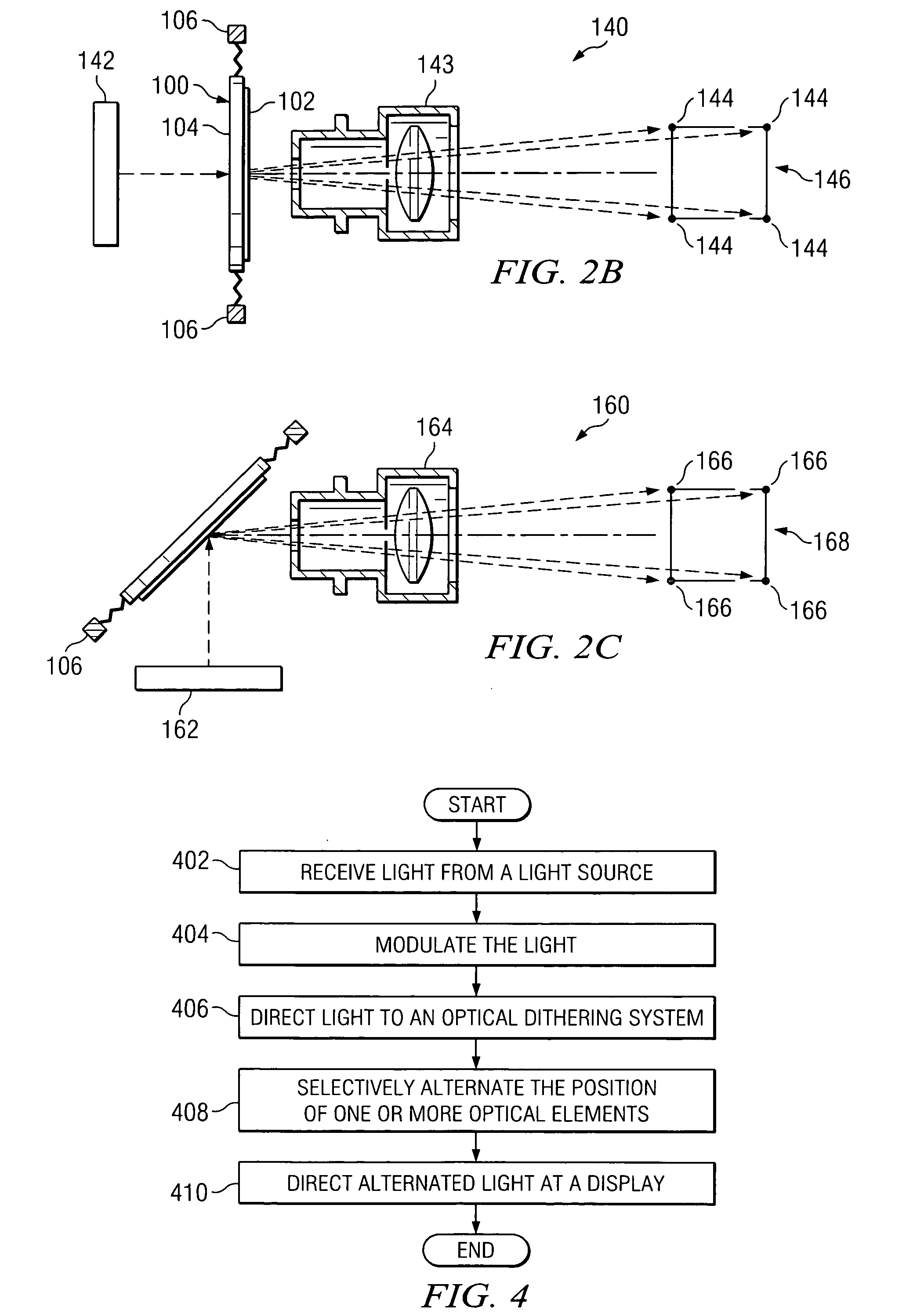
[0005]Some embodiments of the invention provide numerous technical advantages. Some embodiments may benefit from some, none, or all of these advantages. For example, according to one embodiment, a single optical element may be configured such that the position of the element is adjustable with respect to two independent axes of rotation. By selective manipulation of the optical element about the multiple axes of revolution, the image transmitted by the optical element may be displaced by ½ pixel and four on-screen pixels may be generated with a single DMD mirror. Because a single optical element is used to achieve the desired increase in resolution, however, the configuration of the optical dithering system may have a low number of part counts and require a relatively small amount of space in the projection path. Additionally, because the light is directed through or reflected by only a single optical element, lumens and contrast may be maintained at sufficient levels while perceived resolution is increased by a factor of at least four.
[0006]According to another embodiment, multiple, single-axis optical elements may be positioned in series to result in a similar manipulation of the light transmitted by and / or reflected by the optical elements. Specifically, by selectively manipulating each of the two optical elements about an independent axis of rotation, the image transmitted by the combined optical elements may be displaced by ½ pixel and four on-screen pixels may be generated with a single DMD mirror. Because two or more optical elements are used, however, crosstalk between the two axes of rotation may be minimized. Additionally, a greater degree of freedom and control may be obtained with respect to the movement of the respective optical elements. Because vibration modes are controlled, picture quality is improved.

Problems solved by technology

Because a single optical element is used to achieve the desired increase in resolution, however, the configuration of the optical dithering system may have a low number of part counts and require a relatively small amount of space in the projection path.

Method used


Image

  • Method and apparatus using a dual axis optical dithering system to increase a perceived resolution of a display
  • Method and apparatus using a dual axis optical dithering system to increase a perceived resolution of a display
  • Method and apparatus using a dual axis optical dithering system to increase a perceived resolution of a display

Examples


Embodiment Construction

[0013]Embodiments of the invention and its advantages are best understood by referring to FIGS. 1-4 of the drawings, like numerals being used for like and corresponding parts of the various drawings.

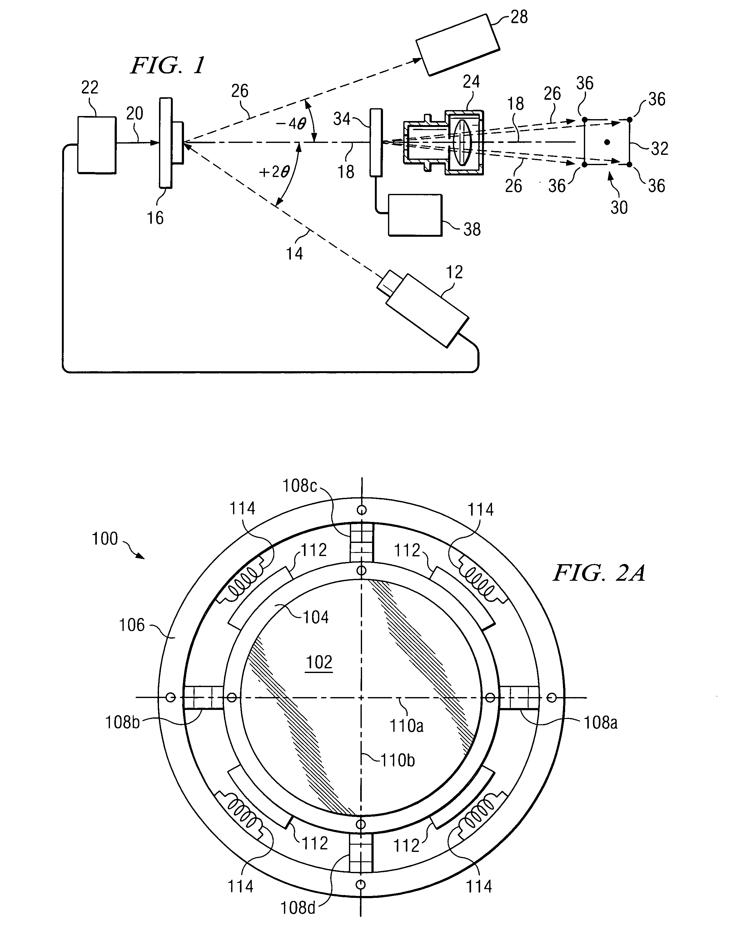
[0014]FIG. 1 is a schematic diagram illustrating one embodiment of a portion of a projection display system 10 for displaying an image with increased perceived resolution. In this example, projection display system 10 includes a light source module 12 capable of generating illumination light beams 14. Light beams 14 are directed from light source module 12 to a modulator 16. Modulator 16 may comprise any device capable of selectively communicating at least some of the received light beams along a projection light path 18. In various embodiments, modulator 16 may comprise a spatial light modulator, such as, for example, a liquid crystal display or a light emitting diode modulator.

[0015]In this particular embodiment, modulator 16 comprises a digital micro-mirror device (DMD). The DMD is a ...


PUM


Abstract

According to one embodiment, a method of increasing a perceived resolution of a display includes directing light at an optical dithering system. The position of one or more optical elements associated with the optical dithering system is selectively alternated between a first set of positions relative to a first axis of rotation and a second set of positions relative to a second axis of rotation. As a result, light is alternately directed to at least four different locations on the display, thereby increasing the perceived resolution of the display.

Description

TECHNICAL FIELD OF THE INVENTION[0001]This invention relates generally to display systems and more particularly to a method and system using a dual axis optical dithering system to increase a perceived resolution of a display.BACKGROUND OF THE INVENTION[0002]Televisions and other types of displays are pervasive in today's society. Recent years have seen the introduction of higher definition displays. Engineers continue to try to increase the resolution of displays to provide better picture quality, but also face constraints associated with providing such increased resolution.[0003]One approach for increasing the resolution of a display involves dithering. increasing a perceived resolution of a display by a user. Rather than providing more pixels, a first image is displayed including a set number of pixels corresponding to the same number of sample data points of the image to be displayed. Then at a time period very close to the display of the first image, a second image is displayed...

Claims


Application Information

Patent Timeline
Patent Type & Authority Applications(United States)
IPC IPC(8): G09G3/34
CPCG09G3/22G02B26/0841
Inventor PENN, STEVEN M.SMITH, STEVEN E.
Owner TEXAS INSTR INC
Learn More