Surgical spacer

Inactive Publication Date: 2007-11-29
WARSAW ORTHOPEDIC INC
View PDF9 Cites 198 Cited by
  • Summary
  • Abstract
  • Description
  • Claims
  • Application Information

AI Technical Summary

Benefits of technology

[0011]Briefly, the present invention satisfies the need for improvements to surgical spacers by providing a flexible container that is fillable in situ, together with at least a partial structure for the flexible container. In this way, the spacer is customizable, de

Problems solved by technology

However, all devices require an open technique to be implanted, and many require destroying important anatomical stabilizers, such as the supraspinous ligament.
Current devices f

Method used


Image

  • Surgical spacer
  • Surgical spacer
  • Surgical spacer

Examples


Example

[0025]A surgical spacer of the present invention can be formed in situ during a procedure. The spacer includes two basic aspects: a flexible container, and a structure for at least part of the container. The flexible container can be filled or injected though an optional conduit after placement. Further, the structure may be folded in some aspects. Together with an unfilled container, in some aspects, the spacer can create a smaller footprint during implantation, which is less invasive, requires less tissue disruption for creating access for implantation, and allows the spacer to conform to the patient's anatomy. Once filled, the structure provides support and containment for the container, reducing the chances of complications like bulging of the container.

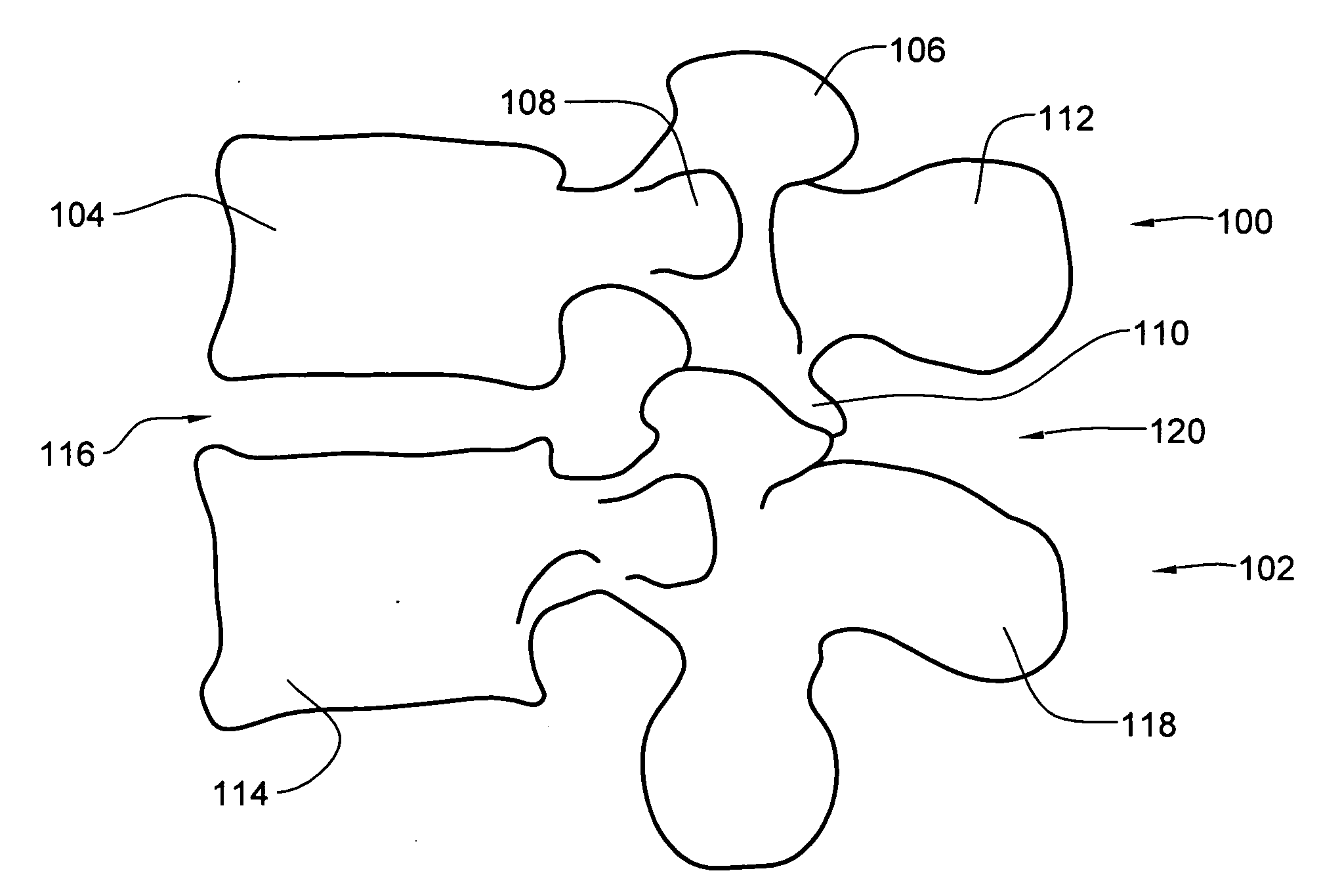
[0026]FIG. 1 depicts adjacent vertebrae 100, 102 of the lumbar region of a human spinal column. As known in the art, each vertebrae comprises a vertebral body (e.g., vertebral body 104), a superior articular process (e.g., superi...


PUM

PropertyMeasurementUnit
Stiffnessaaaaaaaaaa
Stiffnessaaaaaaaaaa
Flow rateaaaaaaaaaa

Abstract

An interspinous spacer for placement between adjacent spinous processes includes a flexible, fillable container (e.g., a bag or balloon) for containing a material that is compressible during end use, for example, silicone after curing. The container is impermeable to the material it will be filled with. A fabric mesh, for example, made of PET fabric, provides structure for and containment of the container. The material can be injected into the container through an optional conduit, for example, a one-way valve.

Description

CROSS-REFERENCE TO RELATED APPLICATIONS / PATENTS[0001]This application contains subject matter which is related to the subject matter of the following applications, each of which is assigned to the same assignee as this application and filed on the same day as this application. Each of the below listed applications is hereby incorporated herein by reference in its entirety:[0002]“Surgical Spacer with Shape Control,” by Lange et al. (Attorney Docket No. P23190.00).[0003]“Systems and Methods for Adjusting Properties of a Spinal Implant,” by Lange et al. (Attorney Docket No. P23186.00); andTECHNICAL FIELD[0004]The present invention generally relates to surgical spacers for spacing adjacent body parts. More particularly, the present invention relates to surgical spacers having a flexible container for containing a material that is compressible during end use, the container being substantially impermeable to the material, and a structure for at least part of the container when containing ...

Claims


Application Information

Patent Timeline
IPC IPC(8): A61F2/44
CPCA61B17/7065A61B2017/00557A61F2002/4495A61F2/442A61F2/441
Inventor ANDERSON, KENT M.
Owner WARSAW ORTHOPEDIC INC
Why Eureka
Try Eureka