Pattern shape evaluation apparatus, pattern shape evaluation method, semiconductor device manufacturing method, and program

a technology of pattern shape and evaluation method, which is applied in the field of pattern shape evaluation apparatus, pattern shape evaluation method, semiconductor device manufacturing method, and program, can solve the problems of reducing the throughput of measurement, inability to know the change in the whole shape of the pattern, and often distorted actual wafers

Inactive Publication Date: 2007-12-06
KK TOSHIBA
View PDF11 Cites 5 Cited by
  • Summary
  • Abstract
  • Description
  • Claims
  • Application Information

AI Technical Summary

Problems solved by technology

However, when the shape of the pattern is complicated, it is impossible to know a change in the whole shape of the pattern if the dimensional measurement is carried out at one place alone.
The number of measurement points has to be increased to know the overall change, but this decreases the throughput of the measurement.
However, the shape of a pattern on an actual wafer is often distorted with respect to design data, and this cause difficulty in the alignment.
Moreover, the degree of the distortion is not uniform among a plurality of patterns present in an acquired image, and unpredictable distortions are also found.
If such an actual pattern is to be superposed on the design data, a situation arises where matching suitable for evaluation can not be achieved due to the influence of the moved actual pattern.
However, when the amount of the positional difference has changed due to a change of process conditions, questionable patterns may be contained in an assumed ROI.
Moreover, in the case of a pattern having a complicated shape instead of the above-mentioned simple line pattern, it is not possible for a rectangular ROI to deal with such a pattern, and a problem arises in which the setting of the ROI itself becomes troublesome.

Method used


Image

  • Pattern shape evaluation apparatus, pattern shape evaluation method, semiconductor device manufacturing method, and program
  • Pattern shape evaluation apparatus, pattern shape evaluation method, semiconductor device manufacturing method, and program
  • Pattern shape evaluation apparatus, pattern shape evaluation method, semiconductor device manufacturing method, and program

Examples


first embodiment

(2) First Embodiment of Pattern Shape Evaluation Method

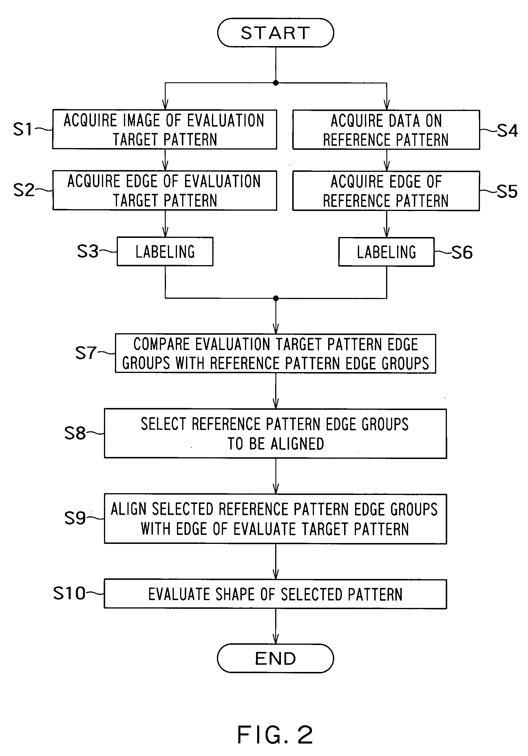
[0072]FIG. 2 is a flowchart showing a schematic procedure of a pattern shape evaluation method according to the present embodiment. It is to be noted that a case will hereinafter be taken as an example where the shape of a pattern is evaluated using an SEM image acquired by an SEM unit, but the present invention is not limited thereto and can be applied an image acquired by any other unit such as an optical image acquiring unit. However, the use of the SEM image is preferable at the present moment because it is necessary to acquire an image of a pattern with higher magnification in order to evaluate the shape of a micropattern of a semiconductor.

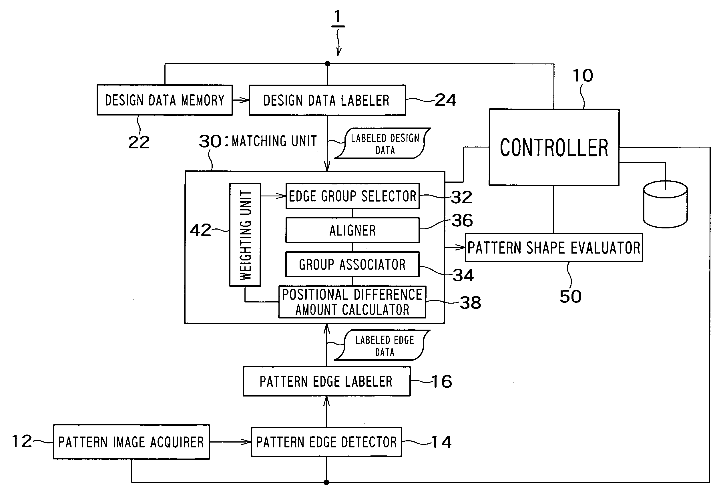
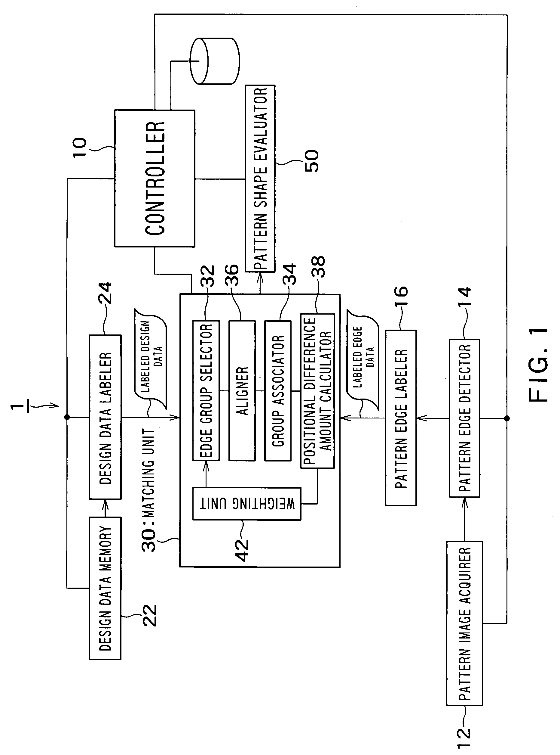
[0073] First, a sample in which an evaluation target pattern is formed is brought in the SEM unit, and an image of the pattern is acquired (step S1) and supplied to the pattern image acquirer 12. Thus, for example, an observation image as shown in FIG. 3 is obtained. As shown in FIG. 3,...

second embodiment

(3) Second Embodiment of Pattern Shape Evaluation Method

[0082] While the operator specifies the reference pattern edge group used in the alignment in the embodiment described above, the present embodiment provides a method comprising calculating the amount of the positional difference of edge groups corresponding to each other between the reference pattern and the evaluation target pattern, and using the obtained positional difference amount to automatically specify a pattern.

[0083] Here, the definition of the “positional difference amount” is clarified. The positional difference amount is the amount indicating a difference between a standard point of the image of the evaluation target and a standard point of the standard image (reference image), and is expressed by, for example, horizontal and vertical distances between the standard points.

[0084] To explain more specifically using FIGS. 12A to 12C, when the evaluation target pattern is a cross pattern, a standard point RPt of an ...

third embodiment

(4) Third Embodiment of Pattern Shape Evaluation Method

[0091]FIG. 18 is a flowchart showing a schematic procedure of a pattern shape evaluation method in the present embodiment.

[0092] The present embodiment is characterized by the procedure shown in steps S50 and S51 in FIG. 18. For other steps in the procedure in FIG. 18, 20 is added to the numbers of the steps in the processing procedure in the third embodiment shown in FIG. 13, so that these steps are substantially the same. Therefore, the procedure shown in steps S50 and S51 in FIG. 18 will be described below.

[0093] That is, after completion of realignment and calculation of the positional difference amount (step S49), the weighting unit 42 of the matching unit 30 weights each edge group in accordance with the calculated positional difference amount (step S50). This weighting is set so that, for example, a deviation is obtained for each edge group from an average value of the positional difference amounts of all the edge group...


PUM


Abstract

A pattern shape evaluation method includes acquiring an image of an evaluation target pattern including a plurality of element patterns; detecting edge of the evaluation target pattern from the image; classifying the detected edge of the evaluation target pattern into a plurality of evaluation target pattern edge groups; acquiring edge of a reference pattern serving as an evaluation standard for the element patterns; classifying the edge of the reference pattern into a plurality of reference pattern edge groups; selecting a reference pattern edge group to be aligned with the edge of the evaluation target pattern from the classified reference pattern edge groups; aligning the edge of the selected reference pattern edge group with the edge of the evaluation target pattern; and evaluating the shape of the evaluation target pattern by use of the result of the alignment.

Description

CROSS REFERENCE TO RELATED APPLICATION [0001] This application claims benefit of priority under 35USC §119 to Japanese patent application No. 2006-110120, filed on Apr. 12, 2006, the contents of which are incorporated by reference herein. BACKGROUND OF THE INVENTION [0002] 1. Field of the Invention [0003] The present invention relates to a pattern shape evaluation apparatus, a pattern shape evaluation method, a semiconductor device manufacturing method, and a program. [0004] 2. Related Background Art [0005] Heretofore, in evaluating a pattern of a semiconductor device, an image of the pattern is acquired, the width of the pattern is measured at an arbitrary place from the obtained image, and the width is compared with a preset specification. However, when the shape of the pattern is complicated, it is impossible to know a change in the whole shape of the pattern if the dimensional measurement is carried out at one place alone. The number of measurement points has to be increased to ...

Claims


Application Information

Patent Timeline
Patent Type & Authority Applications(United States)
IPC IPC(8): G06K9/48
CPCG06K9/4609G06V10/443
Inventor MIYANO, YUMIKOMITSUI, TADASHI
Owner KK TOSHIBA
Why Eureka
Try Eureka