
Camera lens module having auto-focusing device

a technology of auto-focusing and camera lens, which is applied in the direction of camera focusing arrangement, printers, instruments, etc., can solve the problems of significantly inferior performance of the camera mounted to a mobile communication terminal to that of the digital camera commercialized at that tim

Inactive Publication Date: 2007-12-06
SAMSUNG ELECTRONICS CO LTD
View PDF10 Cites 55 Cited by
  • Summary
  • Abstract
  • Description
  • Claims
  • Application Information

AI Technical Summary

Benefits of technology

[0010]Accordingly, the present invention has been made to solve the above-mentioned problems occurring in the prior art and provides additional advantages, by providing a camera lens module having an auto-focusing function and is advantageous to miniaturization.

Problems solved by technology

At an early stage in which a camera was initially mounted to a mobile communication terminal, the performance of the camera mounted to a mobile communication terminal was significantly inferior to that of the digital camera commercialized at that time.
However, even though the performance of a camera lens module and the precision of a manufacturing technique thereof have improved and thereby mobile communication terminals gradually make inroads on digital camera markets, when considering the main functions of a mobile communication terminal, i.e., the maintenance of communication and portability, limitations exist in making the performance of the camera mounted to a mobile communication terminal reach the same level as that of a digital camera.
However, in a mobile communication terminal, since the communication maintaining function and portability must be considered, difficulties are caused in providing an optical zoom function, an auto-focusing function and a shake compensation function to the camera incorporated into to a mobile communication terminal.

Method used


Image

  • Camera lens module having auto-focusing device
  • Camera lens module having auto-focusing device
  • Camera lens module having auto-focusing device

Examples


Embodiment Construction

[0020]Hereinafter, embodiments of the present invention will be described with reference to the accompanying drawings. In the following description, the same elements will be designated by the same reference numerals although they are shown in different drawings. For the purposes of clarity and simplicity, a detailed description of known functions and configurations incorporated herein will be omitted as it may make the subject matter of the present invention rather unclear.

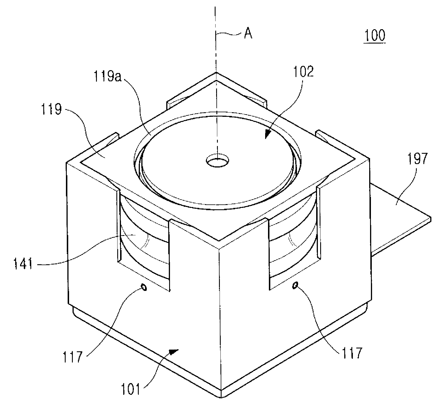
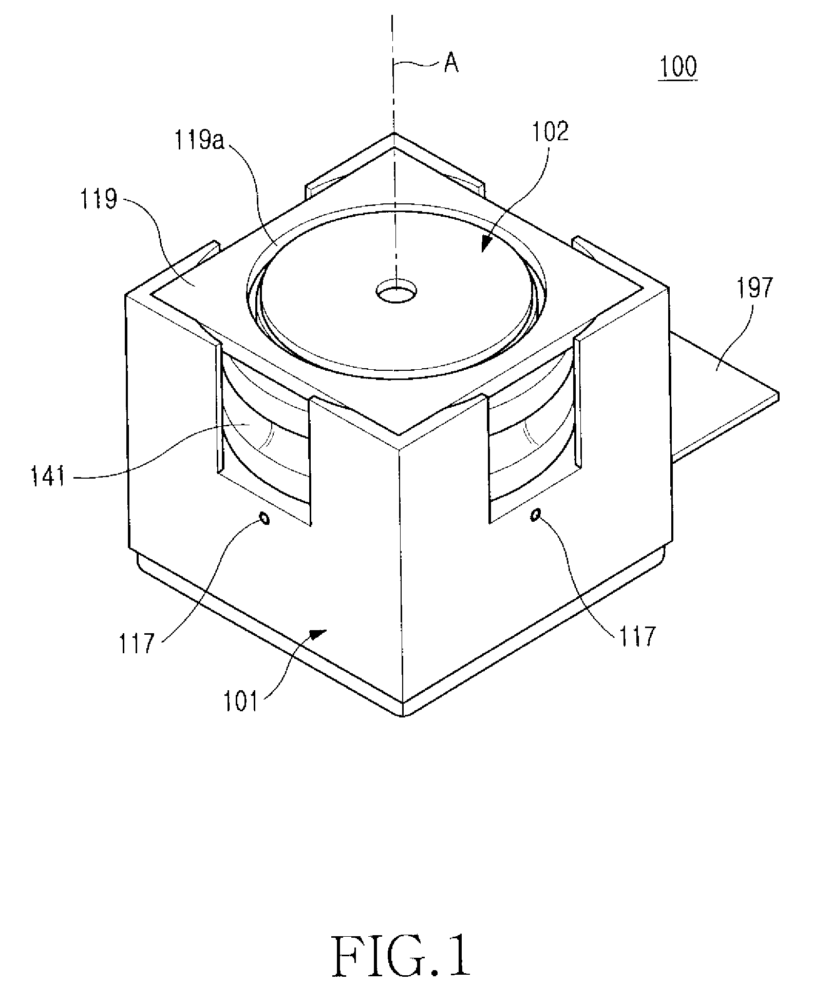
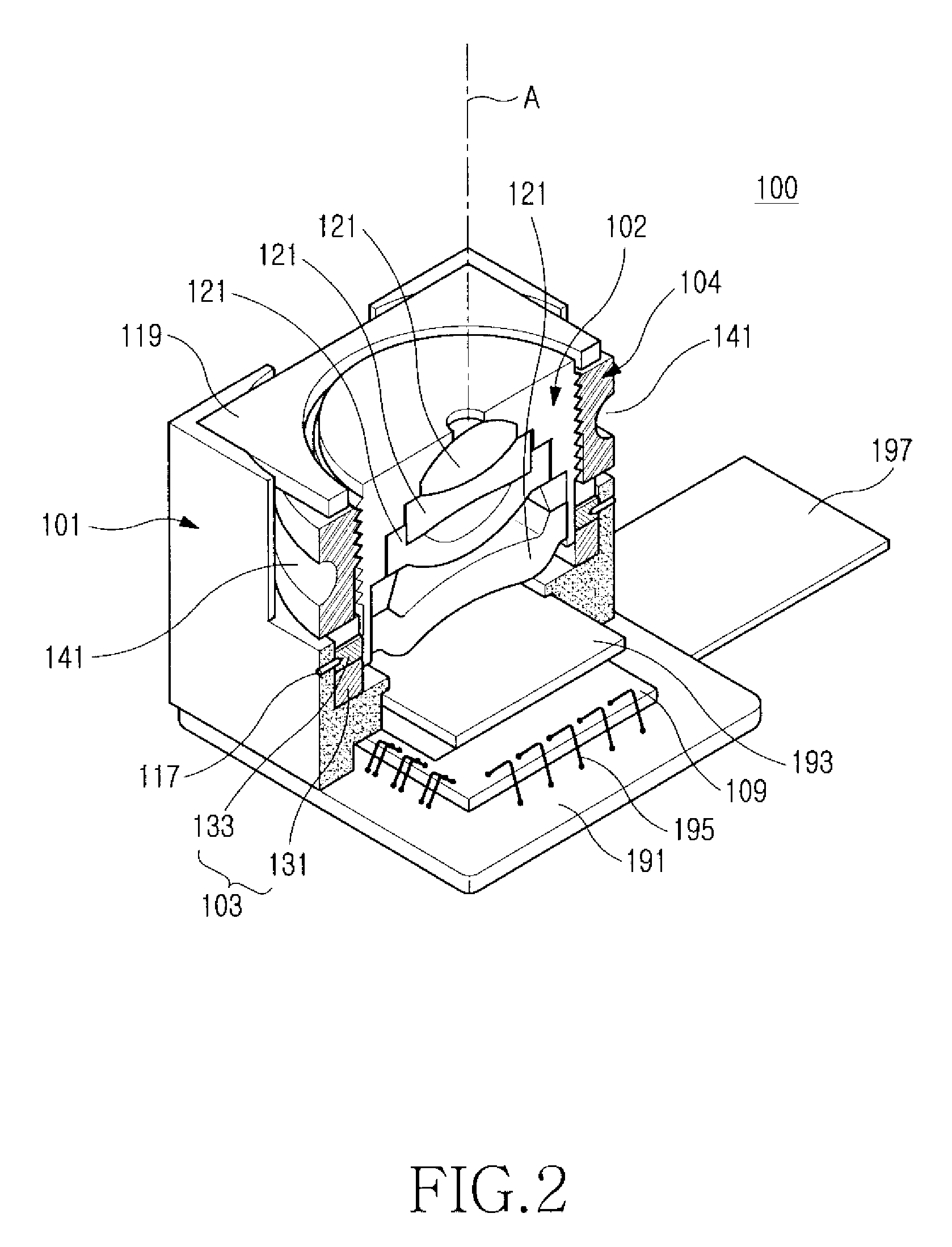
[0021]Referring to FIGS. 1 through 3, a camera lens module 100 having an auto-focusing device in accordance with an embodiment of the present invention includes a rotator 104 (FIG. 3) and a piezoelectric motor 103 (FIG. 3), which are mounted to surround a lens assembly 102, and an image sensor 109. As the lens assembly 102, the rotator 104, and the piezoelectric motor 103 are contained in a module housing 101 (FIG. 1), the camera lens module 100 has a modular configuration.

[0022]The module housing 101 has a hollo...


PUM


Abstract

A camera lens module comprises an image sensor, a lens assembly arranged on an optical axis of the image sensor, a rotator rotatably mounted to surround one part of the lens assembly, a piezoelectric motor mounted to surround the other part of the lens assembly, for providing a driving force for rotating the rotator and a threaded section formed on the lens assembly and the rotator, wherein the threaded section converts rotation of the rotator into linear movement of the lens assembly along the optical axis of the image sensor to adjust a focal distance of the lens assembly. Since the piezoelectric motor is employed as a driving source for auto-focusing, miniaturization can be advantageously attained, whereby the camera lens module having an auto-focusing device can be easily mounted to a digital camera as well as a mobile communication terminal.

Description

CLAIM OF PRIORITY[0001]This application claims the benefit of the earlier filing date, pursuant to 35 USC 119, to that patent application entitled “Camera Lens Module having Auto-Focusing Device,” filed in the Korean Intellectual Property Office on Jun. 1, 2006 and assigned Serial No. 2006-49384, the contents of which are hereby incorporated by reference.BACKGROUND OF THE INVENTION[0002]1. Field of the Invention[0003]The present invention relates to a camera lens module, and more particularly to a camera lens module which is constructed to automatically adjust the focal distance of a lens in an optical unit mounted to a digital camera or a mobile communication terminal.[0004]2. Description of the Related Art[0005]With the development of techniques for miniaturization and light weight of digital cameras, it has become possible to mount a camera to a mobile communication terminal, e.g. cellular telephones personal digital assistant, and mobile communication terminals mounted with an o...

Claims


Application Information

Patent Timeline
Patent Type & Authority Applications(United States)
IPC IPC(8): G03B3/10
CPCG02B7/04G03B3/10G02B13/001G02B7/09
Inventor SHIN, DOO-SIK
Owner SAMSUNG ELECTRONICS CO LTD
Learn More