Transfer coping for dental implants

a technology of dental implants and transfer coping, which is applied in the field of improved pickup type impression coping, can solve the problems of difficult and expensive manufacturing of snap features of this pick-up coping

Inactive Publication Date: 2007-12-06
NOBEL BIOCARE SERVICES AG
View PDF7 Cites 57 Cited by
  • Summary
  • Abstract
  • Description
  • Claims
  • Application Information

AI Technical Summary

Problems solved by technology

However, the snap in features of this pick up coping have proven difficult and expensive to manufacture.

Method used


Image

  • Transfer coping for dental implants
  • Transfer coping for dental implants
  • Transfer coping for dental implants

Examples


Embodiment Construction

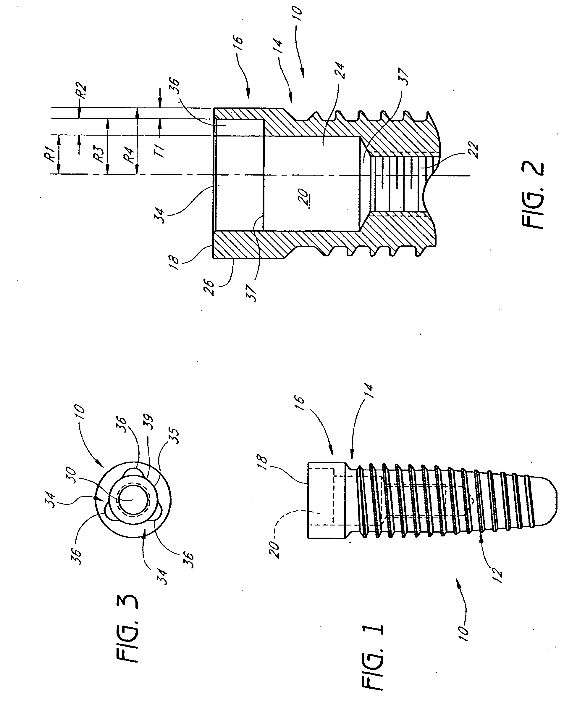
[0029]The embodiments described herein relate to methods and devices that relate to taking an impression of a dental implant which is implanted in a patient's jaw. FIGS. 1-3 illustrate one exemplary embodiment of a dental implant 10, particularly suited for receiving a dental impression coping having certain features and advantages according to one embodiment of the present invention. The dental implant 10 is described in detail in U.S. Pat. No. 6,382,977, and U.S. Pat. No. 6,733,291, the disclosure of which are hereby incorporated herein by reference.

[0030]As shown in FIGS. 1-3, the implant 10 can have an outer surface that is preferably divided into three regions: a body portion 12, a neck region 14, and a top portion 16. The body portion 12 preferably includes threads, and represents the portion of the implant 10 that is placed in either the mandible or the maxilla. A hollow inner cavity 20 can extend from the top portion 16 through a portion of the body portion 12 of the implant...


PUM


Abstract

An impression coping is provided for taking an impression of an implant installed in a patient's mouth. The impression coping comprises an engagement portion, a cover and an impression portion. The engagement portion is adapted to be inserted within an internal cavity of the implant. The engagement portion has a plurality of axially extending protrusions positioned around the periphery for engaging corresponding channels within the internal cavity of the implant. The engagement shaft is thus configured to register the internal orientation of the implant within a patient's jaw. The impression portion of the coping includes one or more embedment features adapted to be embedded in a dental impression material for taking a dental impression thereof.

Description

BACKGROUND OF THE INVENTION[0001]1. Field of the Invention[0002]The present invention relates generally to dental impression copings used in implant dentistry to take impressions of a dental implant site from which accurate models can be constructed. More particularly, the invention relates to an improved pick-up type impression coping.[0003]2. Description of the Related Art[0004]Restoration of an edentulous area of the mouth serves multiple functions, including improved aesthetics, improved mastication, maintenance of crestal bone, and providing for an occlusal stop for a reproducible bite. Restoration can be accomplished using a standard bridge, a removable appliance (a partial or full denture), or a dental implant.[0005]Dental implantation is a procedure for replacing a missing tooth using a dental implant. A dentist reviews radiographs and dental models to determine the proper placement and axial alignment of the implant. The placement of the implant has historically been accomp...

Claims


Application Information

Patent Timeline
Patent Type & Authority Applications(United States)
IPC IPC(8): A61C8/00
CPCA61C8/0001A61C8/005A61C8/0054A61C8/0069A61C8/006A61C8/0065A61C8/0066A61C8/0057
Inventor JORNEUS, LARSHURSON, STEVEN M.
Owner NOBEL BIOCARE SERVICES AG
Why Eureka
Try Eureka