Dispensing cartridge

a technology of dispensing cartridges and cartridges, which is applied in the direction of liquid/fluent solid measurement, containers, dental prosthetics, etc., can solve the problems of low shrinking rate, little ability to form shrink marks, and plastic materials that are difficult to handle in injection moulds to achieve the effect of improving stability

Inactive Publication Date: 2005-03-03
3M ESPE
View PDF9 Cites 6 Cited by
  • Summary
  • Abstract
  • Description
  • Claims
  • Application Information

AI Technical Summary

Benefits of technology

[0009] In view of the above, the present invention provides a dispensing cart

Problems solved by technology

Moreover, the plastic material has to be easy to handle in the injection mould, i.e., low shrinkin

Method used


Image

  • Dispensing cartridge
  • Dispensing cartridge
  • Dispensing cartridge

Examples


Embodiment Construction

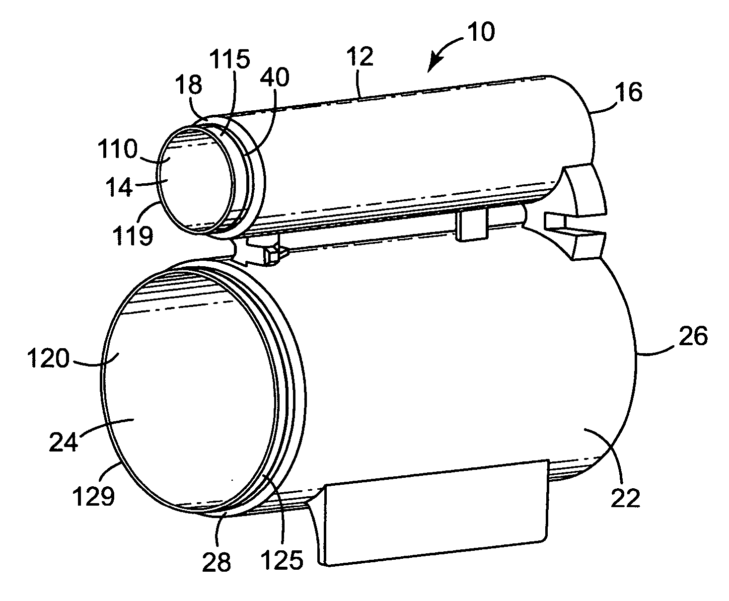
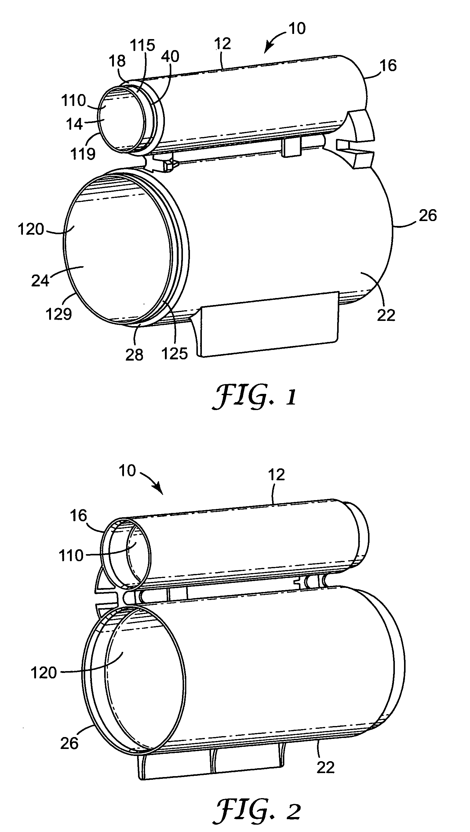
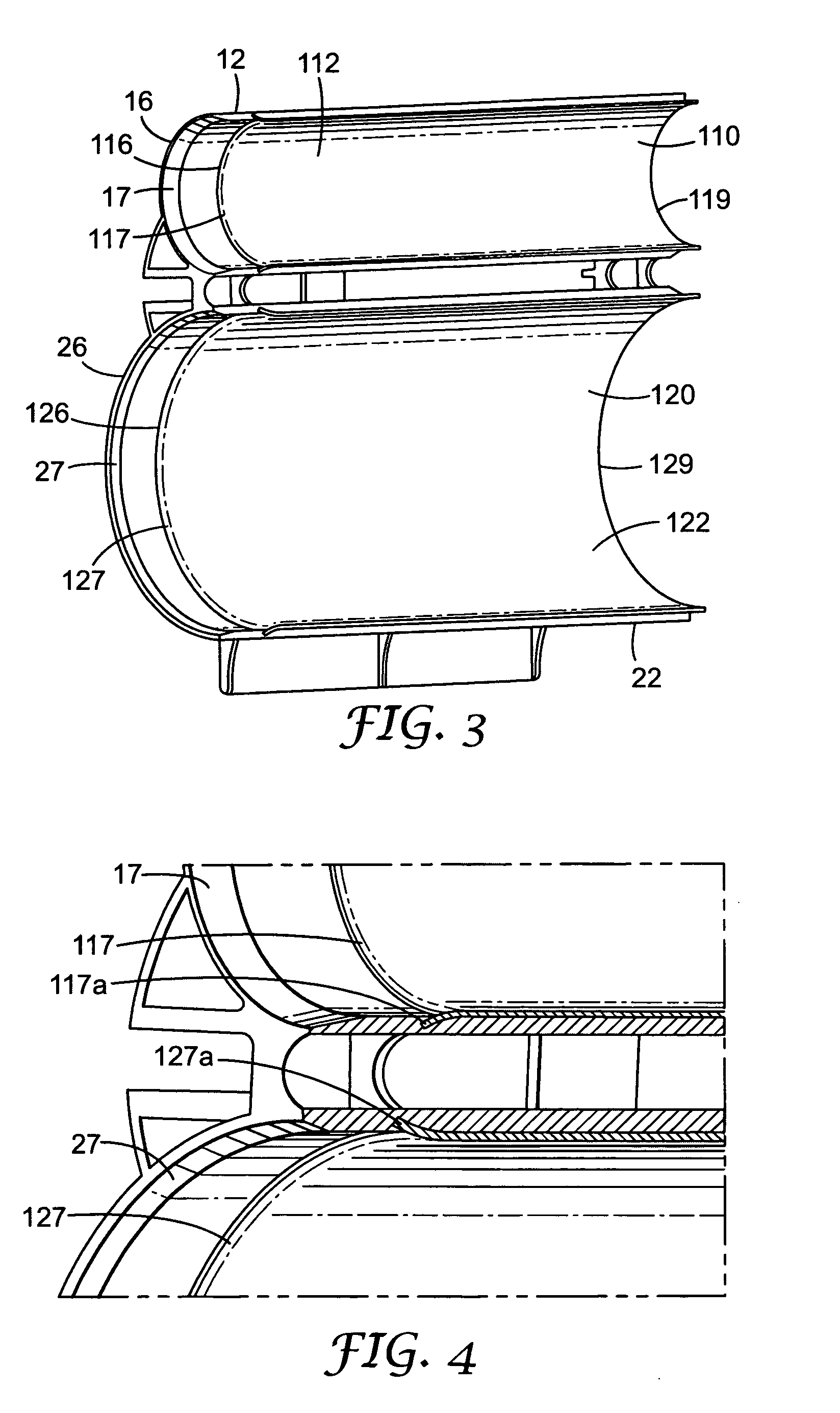
[0030] An example of a dispensing cartridge constructed in accordance with the principles of the present invention is illustrated in FIG. 1 and is broadly designated by reference numeral 10. The cartridge 10 includes a first compartment with a body 12, having an interior chamber 14. In more detail, the body 12 includes an open end 16 and an outlet or outlet opening 18 that is remote from the open end 16. The compartment is elongated and extends from the open end 16 to the outlet opening 18.

[0031] The dispensing cartridge as shown in FIG. 1 comprises a second compartment having a body 22 with interior chamber 24. The body 22 includes an open end 26 and an outlet or outlet opening 28 that is remote from the open end 26. The second compartment is elongated and extends from the open end 26 to the outlet opening 28.

[0032] In the shown embodiment, both compartments comprise a metal reinforcement tube, i.e. tubes 110 and 120. The outer diameters of the metal reinforcement tubes 110 and 1...


PUM


Abstract

The present invention relates to a dispensing cartridge, particularly for dental impression materials, formed from a plastic material having at least one inlet and at least one outlet, and comprising a metal reinforcement tube.

Description

FIELD OF THE INVENTION [0001] This application claims priority from EP Application No. 03013831.7, filed Jun. 18, 2003. [0002] The present invention relates to a dispensing cartridge, particularly for dental impression materials, of the type adapted to be releasably received in an applicator having a moveable plunger. BACKGROUND OF THE INVENTION [0003] A number of dispensing devices are available for dispensing various types of materials. In many instances, the dispensing device is an assembly that includes a reusable dispenser or applicator and a disposable cartridge. The cartridge contains a quantity of a composition or material to be dispensed and is releasably received in a receptacle of the applicator. [0004] In one type of dispensing devices, that include an applicator and a cartridge, the applicator has a plunger that is advanced by the user during a dispensing operation. Often, the plunger is received in an open end of the cartridge and bears against a piston within the cart...

Claims


Application Information

Patent Timeline
IPC IPC(8): A61C5/06A61C9/00A61C5/64A61C5/66B65D81/32
CPCA61C5/062A61C5/064B65D81/3205A61C9/0026A61C5/066A61C5/62A61C5/64A61C5/66
Inventor KNEE, MICHAELMUELLER, DIRKWAGNER, INGO W.
Owner 3M ESPE
Why Eureka
Try Eureka