Transportation machine with energy absorbing structure

a technology of transporting machine and energy-absorbing structure, which is applied in the direction of buffer cars, railway bodies, axle-box lubrication, etc., can solve the problems of large impact on the railway vehicle, the possibility of collision with an unexpected material object during operation, and the inability to effectively dispose of objects

Inactive Publication Date: 2007-12-13
HITACHI LTD
View PDF21 Cites 16 Cited by
  • Summary
  • Abstract
  • Description
  • Claims
  • Application Information

AI Technical Summary

Benefits of technology

[0017]According to this invention, by disposing the energy absorbing member in a form projecting from the driving cab through the window formed on the flying object barrier plate to a position outward of the flying object barrier plate, the energy absorbing member of a large absorbing capacity can be efficiently disposed by utilizing a space of the driving cab provided in the vehicle body. The beam member of the crushable zone including the flying object barrier plate can be firmly placed and connected to the survival zone.
[0018]According to the present invention, the length in the longitudinal direction of the head portion of the transportation machine can be made as short as possible, and the satisfactory transportation machine with the energy absorbing structure in terms of absorption of energy, protection at the time of collision with a flying object and support of the load at the time of a normal operation can be provided.

Problems solved by technology

In a transportation machine represented by a railway vehicle, there is the possibility of occurrence of collision with an unexpected material object during operation.
When the railway vehicle collides with a large material object, a large impact acts on the railway vehicle due to the collision with the material object.
However, the possibility that the flying object penetrates through the vehicle body structure and damages a driver and passengers on board is conceivable.
In such a structure, the energy absorbing member which is disposed on the floor of the driver's cab deforms when the railway vehicle collides with a large obstacle, and therefore, the space of the driving cab is affected, thus making it difficult to secure safety of the crew sufficiently.
Thus, there is the problem to be solved in the respect of utilizing the space of a driving cab provided in a vehicle body and causing the energy material having a large energy absorbing amount to function effectively while securing safety of the crews.

Method used


Image

  • Transportation machine with energy absorbing structure
  • Transportation machine with energy absorbing structure
  • Transportation machine with energy absorbing structure

Examples


Embodiment Construction

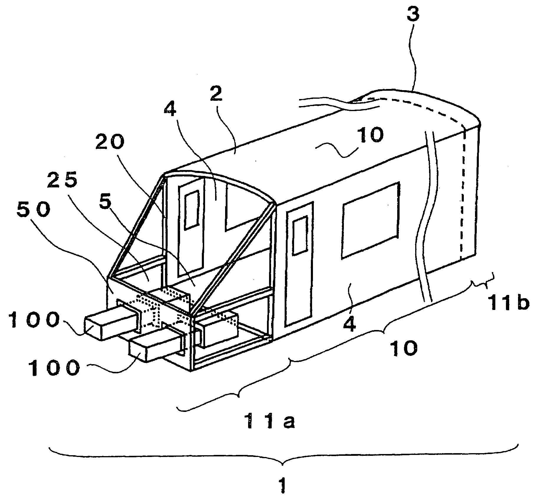
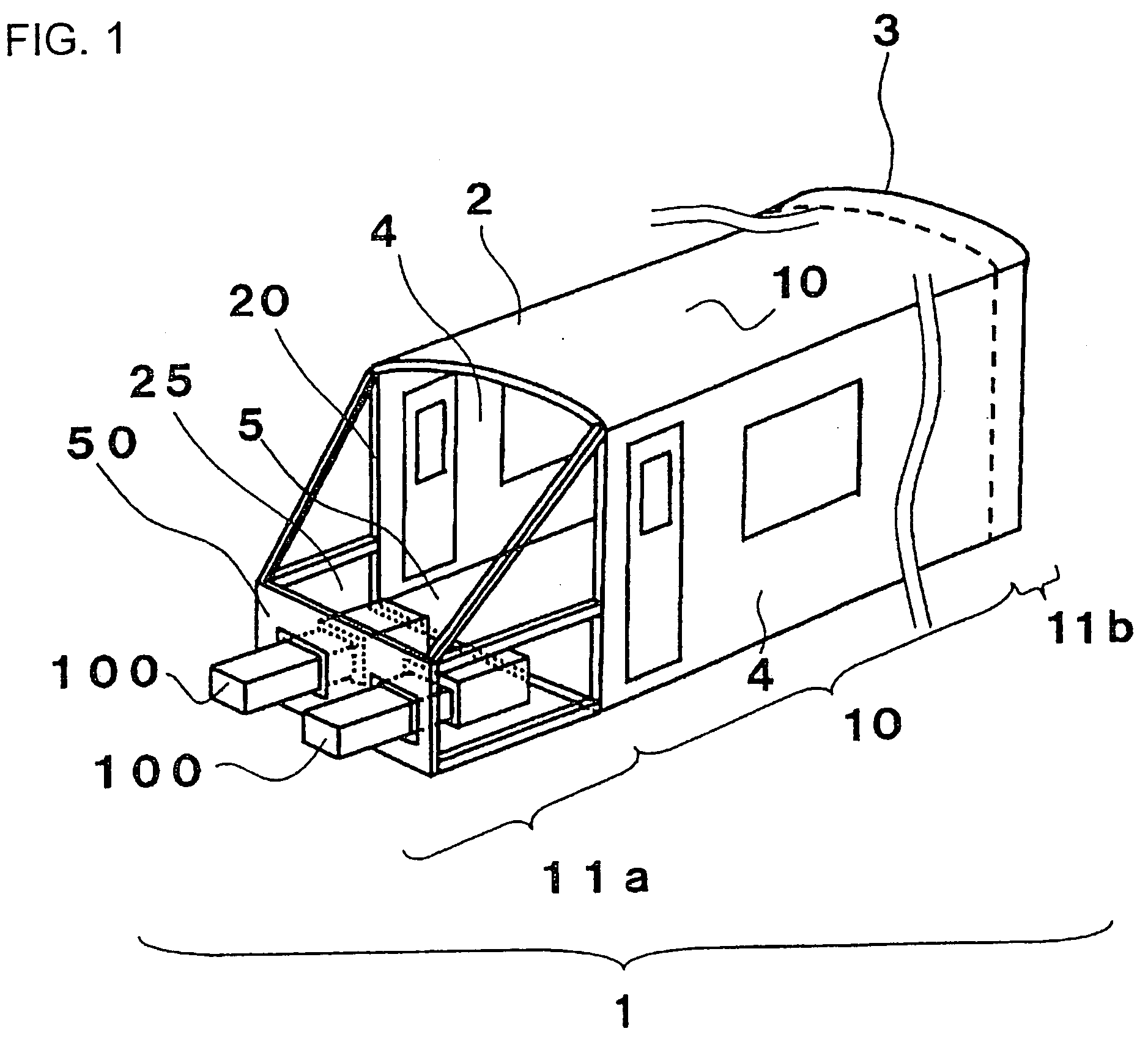
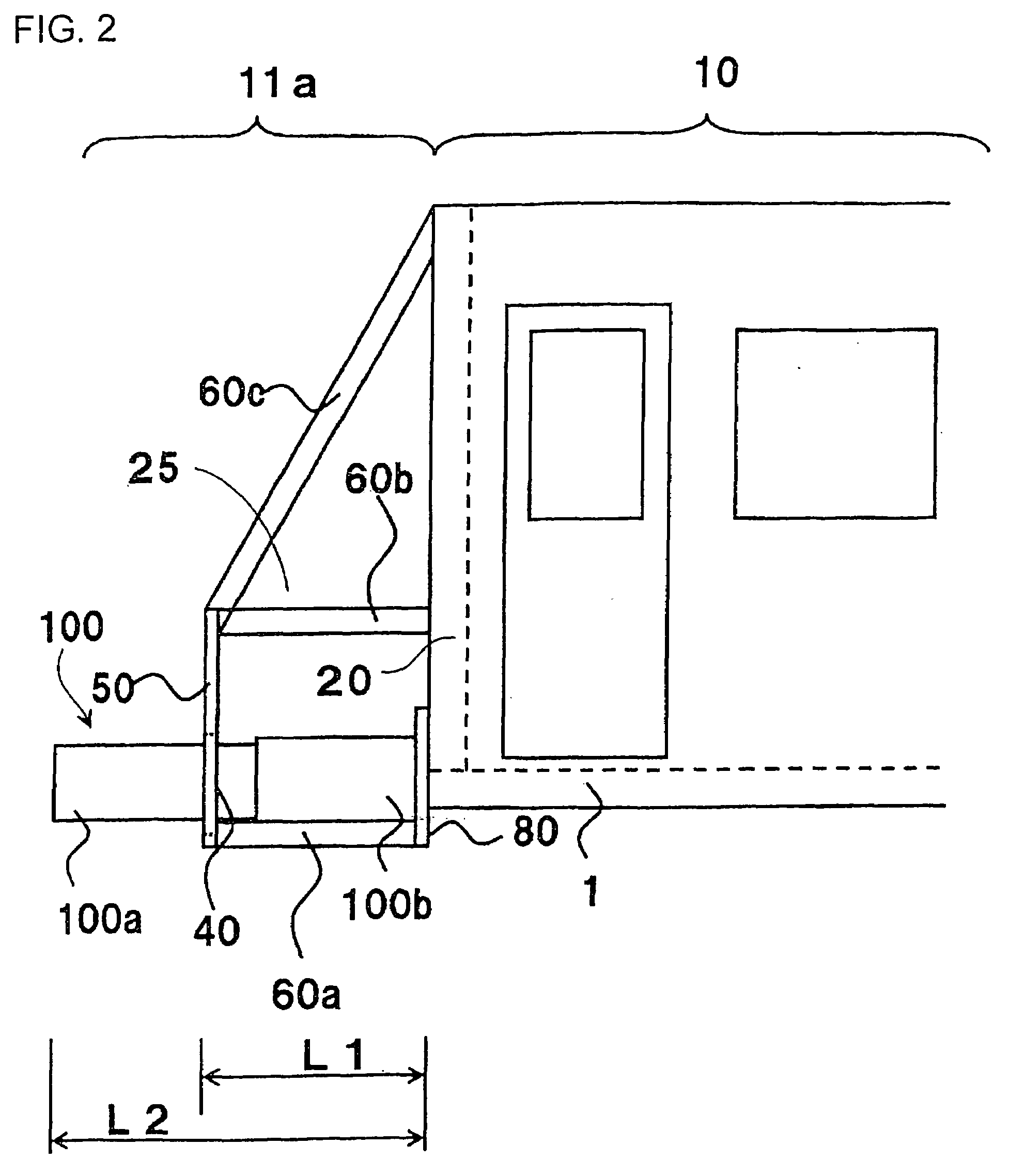
[0027]A first embodiment in the case where the present invention is applied to a railway vehicle body structure when a transportation machine is a railway vehicle will be described with reference to FIGS. 1 to 4.

[0028]First, a structure of the railway vehicle body structure will be described with reference to FIG. 1. A railway vehicle body structure 1 is constructed by a roof body structure 2 which forms a roof, end body structures 3 which form surfaces for closing both ends with respect to a vehicle body longitudinal direction, side body structures 4 which form left and right surfaces with respect to the vehicle body longitudinal direction, and an underframe 5 which forms a floor surface. The underframe 5 has high rigidity against a compression load in the longitudinal direction. Windows and openings for entrance / exit are formed in the side body structure 4. The railway vehicle body structure 1 having such a basic structure has a survival zone 10 which protects the lives of passeng...


PUM


Abstract

For a transportation machine such as a railway vehicle, a space for a driver is secured while collision energy is absorbed at a time of collision with a large obstacle, and entry of a flying object into a driving cab is prevented by a rigid structure at a time of collision with the flying object. Windows 40, 40 are provided in a flying object barrier plate 50 provided at a tip end portion of a driving cab 25, and energy absorbing members 100, 100 are penetrated through the windows 40, 40 to be disposed in a form extending outward of the flying object barrier plate 50 from an inside of the driving cab 25. The energy absorbing members 100, 100 of a large absorbing capacity can be efficiently disposed by utilizing a space of the driving cab 25 provided in a vehicle body. A beam member of a crushable zone 11a including the flying object barrier plate 50 is firmly placed and can be connected to a survival zone 10.

Description

[0001]The present application is based on and claims priority of Japanese patent application No. 2006-131260 filed on May 10, 2006, the entire contents of which are hereby incorporated by reference.BACKGROUND OF THE INVENTION[0002]1. Field of the Invention[0003]The present invention relates to a transportation machine with an energy absorbing structure, such as a railway vehicle and a monorail vehicle.[0004]2. Description of the Related Art[0005]In a transportation machine represented by a railway vehicle, there is the possibility of occurrence of collision with an unexpected material object during operation. Citing the past collision examples of railway vehicles as the example, as the material objects which unexpectedly collide with railway vehicles, there are various kinds of things including large things such as road vehicles, trees, and railway vehicles, and small things such as stones, snowballs and components of the opposing vehicles.[0006]Here, the case where a railway vehicl...

Claims


Application Information

Patent Timeline
Patent Type & Authority Applications(United States)
IPC IPC(8): B61D17/00
CPCB61D17/06B61D15/06B61F19/04
Inventor KAWASAKI, TAKESHIYAMAGUCHI, TAKASHIMOCHIDA, TOSHIHIKOYAMAMOTO, TAKAHISA
Owner HITACHI LTD
Why Eureka
Try Eureka