Method and apparatus to control hydraulic pressure in an electro-mechanical transmission

a technology of electro-mechanical transmission and control system, which is applied in the direction of rotary clutches, gearings, fluid couplings, etc., can solve the problems of inoperable engine-driven hydraulic pumps, inability to maintain fluidic pressure in the hydraulic circuit, and currently applied torque-transfer clutches may deactiva

Inactive Publication Date: 2007-12-13
GM GLOBAL TECH OPERATIONS LLC
View PDF26 Cites 179 Cited by
  • Summary
  • Abstract
  • Description
  • Claims
  • Application Information

AI Technical Summary

Benefits of technology

[0007]Another aspect of the invention includes a control system for a powertrain comprising an engine operatively connected to a transmission having a main hydraulic pump and an auxiliary hydraulic pump each pump operative to selectively supply pressurized fluid to a hydraulic circuit for the transmission. The control system comprises a distributed control module system operative to execute a control scheme operable to determine a pressure in the hydraulic circuit, determine a desired pressure in the hydraulic circuit, and, control operation of the auxiliary hydraulic pump based upon the hydraulic pressure,

Problems solved by technology

Under such conditions, the engine-driven hydraulic pump is inoperative and unable to maintain fluidic pressure in th

Method used


Image

  • Method and apparatus to control hydraulic pressure in an electro-mechanical transmission
  • Method and apparatus to control hydraulic pressure in an electro-mechanical transmission
  • Method and apparatus to control hydraulic pressure in an electro-mechanical transmission

Examples


Embodiment Construction

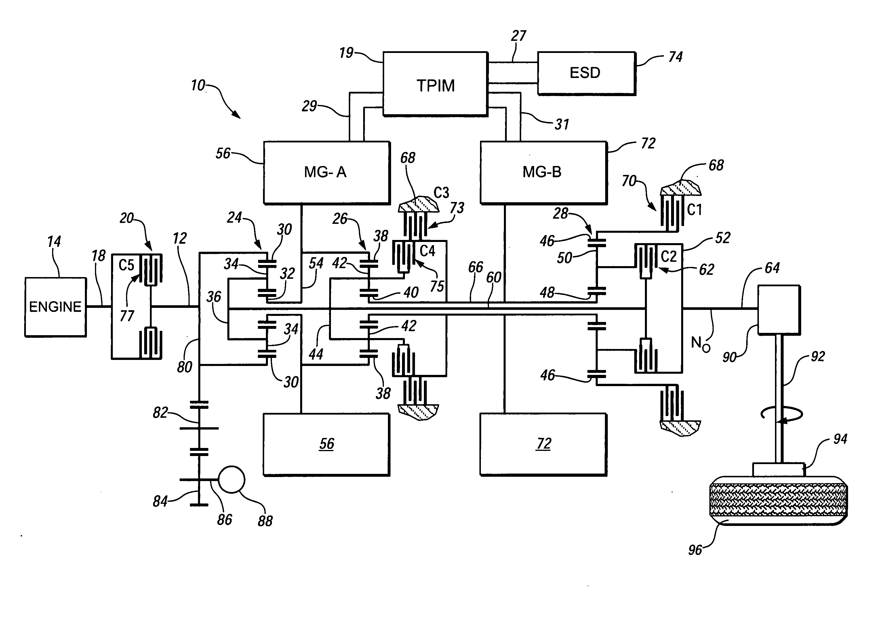
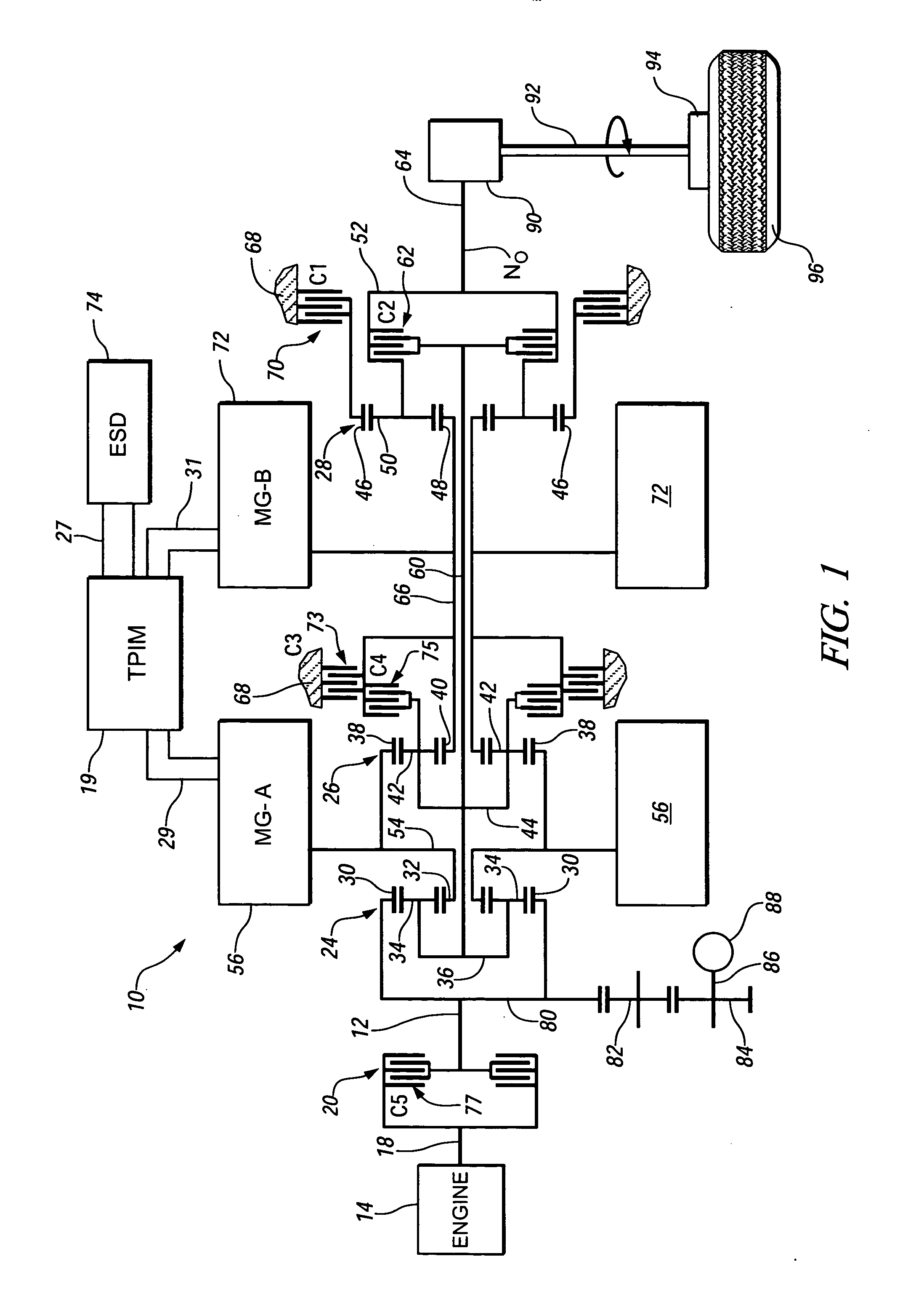
[0015]Referring now to the drawings, wherein the showings are for the purpose of illustrating the invention only and not for the purpose of limiting the same, FIGS. 1 and 2 depict a system comprising an engine 14, transmission 10, control system, and driveline which has been constructed in accordance with an embodiment of the present invention.

[0016]Mechanical aspects of exemplary transmission 10 are disclosed in detail in commonly assigned U.S. Pat. No. 6,953,409, entitled “Two-Mode, Compound-Split, Hybrid Electro-Mechanical Transmission having Four Fixed Ratios”, which is incorporated herein by reference. The exemplary two-mode, compound-split, electromechanical transmission embodying the concepts of the present invention is depicted in FIG. 1. The transmission 10 has an input shaft 12 preferably directly driven by engine 14. A transient torque damper 20 is incorporated between the output shaft 18 of the engine 14 and the input member 12 of the transmission 10. The transient torqu...


PUM


Abstract

The invention comprises a method, an article, and a control system for controlling a powertrain having a main and an auxiliary hydraulic pump, with each pump operative to supply hydraulic fluid to a hydraulic circuit of the transmission. It includes determining a main pressure and a desired main pressure, and controlling the auxiliary hydraulic pump. Determining a main pressure in the hydraulic circuit comprises estimating hydraulic pressure. The auxiliary pump is controlled to an operating speed. Control of flow from the auxiliary and main pumps can comprise an exclusive ‘either-or’ flow, or a blended flow.

Description

TECHNICAL FIELD[0001]This invention pertains generally to an electromechanical transmission device, and more specifically to a control system for a hydraulic system of the transmission device.BACKGROUND OF THE INVENTION[0002]An electromechanical transmission device can be used as an element in a hybrid powertrain system to control torque and speed output to a driveline transmitted from torque-generative devices. The torque-generative devices typically comprise an internal combustion engine and electric machines. One hybrid powertrain architecture includes a two-mode, compound-split, electro-mechanical transmission operative to receive torque input from the torque-generative devices. Management of the torque inputs to achieve an output includes selective actuation of torque-transfer devices, or clutches, contained in the transmission. Actuation of each clutch is effected via selectively applied hydraulic pressure from a hydraulic circuit. Pressurized fluid through the hydraulic circu...

Claims


Application Information

Patent Timeline
IPC IPC(8): B60K17/00
CPCB60K1/02Y02T10/6239B60K6/40B60K6/445B60K6/547B60W10/02B60W10/115B60W10/30B60W20/00B60W2550/12F16H3/728F16H61/0031F16H2037/0866F16H2037/102F16H2037/106F16H2200/201F16H2200/2043B60K6/365B60W2555/20Y02T10/62B60W20/30
Inventor SAH, JY-JEN F.SNYDER, BRYAN R.
Owner GM GLOBAL TECH OPERATIONS LLC
Why Eureka
Try Eureka