Method and apparatus for quantifying quiescent period temperature effects upon an electric energy storage device

a technology of quiescent period and temperature effect, applied in secondary cell servicing/maintenance, process and machine control, instruments, etc., can solve the problems of significant effect on battery service life, limited battery charge/discharge performance, and diminished service li

Active Publication Date: 2007-12-13
GM GLOBAL TECH OPERATIONS LLC
View PDF7 Cites 142 Cited by
  • Summary
  • Abstract
  • Description
  • Claims
  • Application Information

AI Technical Summary

Benefits of technology

[0008]A method to determine an effect of temperature during a quiescent period of an electrical energy storage device operation upon life expectancy of an electrical energy storage device includes determining a weighted average temperature of the electrical energy storage device during the quiescent period. The weighted average temperature is based upon an average temperature of the electrical energy storage device during the quiescent period and a temperature of the electrical energy storage device substantially contemporaneous with the start of the quiescent period. Further, the method includes determining a resting temperature factor for the electrical energy storage device based upon the weighted average temperature of the electrical energy storage device during the quiescent period.

Problems solved by technology

However, cold operating temperature introduces limits in battery charge / discharge performance until temperature of the pack is increased.
A warm battery pack is more able to supply required power to the vehicle propulsion system, but continued warm temperature operation may result in diminished service life.
However, the ambient environmental conditions may have significant effect upon battery service life.
The ohmic resistance of the battery pack is typically flat during much of the service life of the vehicle and battery pack however, thus preventing a reliable estimate of real-time state-of-life (‘SOL’) of the battery pack throughout most of the service life.
Furthermore, service life of a battery pack is affected by resting temperature, i.e. life of a battery pack system increases as resting temperature of the battery pack decreases.

Method used


Image

  • Method and apparatus for quantifying quiescent period temperature effects upon an electric energy storage device
  • Method and apparatus for quantifying quiescent period temperature effects upon an electric energy storage device
  • Method and apparatus for quantifying quiescent period temperature effects upon an electric energy storage device

Examples


Embodiment Construction

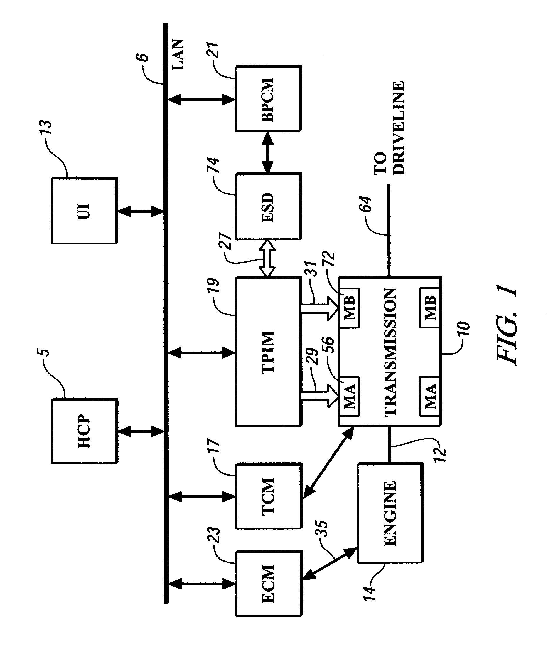
[0013]Referring now to the drawings, wherein the showings are for the purpose of illustrating the invention only and not for the purpose of limiting the same, FIG. 1 shows a control system and an exemplary hybrid powertrain system which has been constructed in accordance with an embodiment of the invention. The exemplary hybrid powertrain system comprises a plurality of torque-generative devices operable to supply motive torque to a transmission device, which supplies motive torque to a driveline. The torque-generative devices preferably comprise an internal combustion engine 14 and first and second electric machines 56, 72 operable to convert electrical energy supplied from an electrical storage device (ESD) 74 to motive torque. It is understood that ESD may include one or more batteries or alternative electrical energy storage apparatus. The exemplary transmission device 10 comprises a two-mode, compound-split electromechanical transmission having four fixed gear ratios and two co...


PUM


Abstract

A electrical energy storage device may experience quiescent periods of operation. A method is disclosed effective to account for the effects that temperature during quiescent periods has upon the electrical energy storage device.

Description

TECHNICAL FIELD[0001]This invention pertains generally to life expectancy of an electrical energy storage device. More particularly, the invention is concerned with the effects that periods of rest have upon such life expectancy.BACKGROUND OF THE INVENTION[0002]Various hybrid powertrain systems use electrical energy storage devices to supply electrical energy to electrical machines, which are operable to provide motive torque, often in conjunction with an internal combustion engine. One such hybrid powertrain architecture comprises a two-mode, compound-split, electromechanical transmission which utilizes an input member for receiving power from a prime mover power source and an output member for delivering power from the transmission to a vehicle driveline. First and second electric machines, i.e. motor / generators, are operatively connected to an energy storage device for interchanging electrical power therebetween. A control unit is provided for regulating the electrical power inte...

Claims


Application Information

Patent Timeline
Patent Type & Authority Applications(United States)
IPC IPC(8): H02J7/04
CPCG01R31/3613G01R31/3662H01M10/486H01M10/4285H01M10/48G01R31/3675G01R31/3832G01R31/389G01R31/374Y02E60/10
Inventor ZETTEL, ANDREW M.HEAP, ANTHONY H.
Owner GM GLOBAL TECH OPERATIONS LLC
Why Eureka
Try Eureka