Light Source and Vehicle Lamp

a technology for light sources and vehicles, applied in semiconductor devices, light sources, transportation and packaging, etc., can solve the problems of large light distribution pattern and unfavorable led light source b>2/b> for vehicle lamps, and achieve the effect of favorable light distribution pattern

Active Publication Date: 2007-12-13
STANLEY ELECTRIC CO LTD
View PDF5 Cites 41 Cited by
  • Summary
  • Abstract
  • Description
  • Claims
  • Application Information

AI Technical Summary

Benefits of technology

[0020] The presently disclosed subject matter has been devised in view of the above and other characteristics, desires, and problems in the art, and to make certain changes to the ex...

Problems solved by technology

Thus, the LED light source 2 is not favorable for a vehicle lamp due to requiring a high luminous flux.
However, such a vehicle lamp has problems such as a short focus distance resu...

Method used


Image

  • Light Source and Vehicle Lamp
  • Light Source and Vehicle Lamp
  • Light Source and Vehicle Lamp

Examples


Embodiment Construction

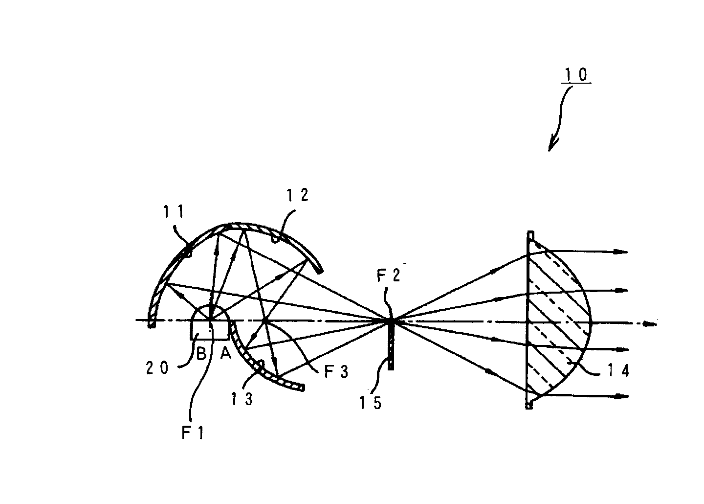
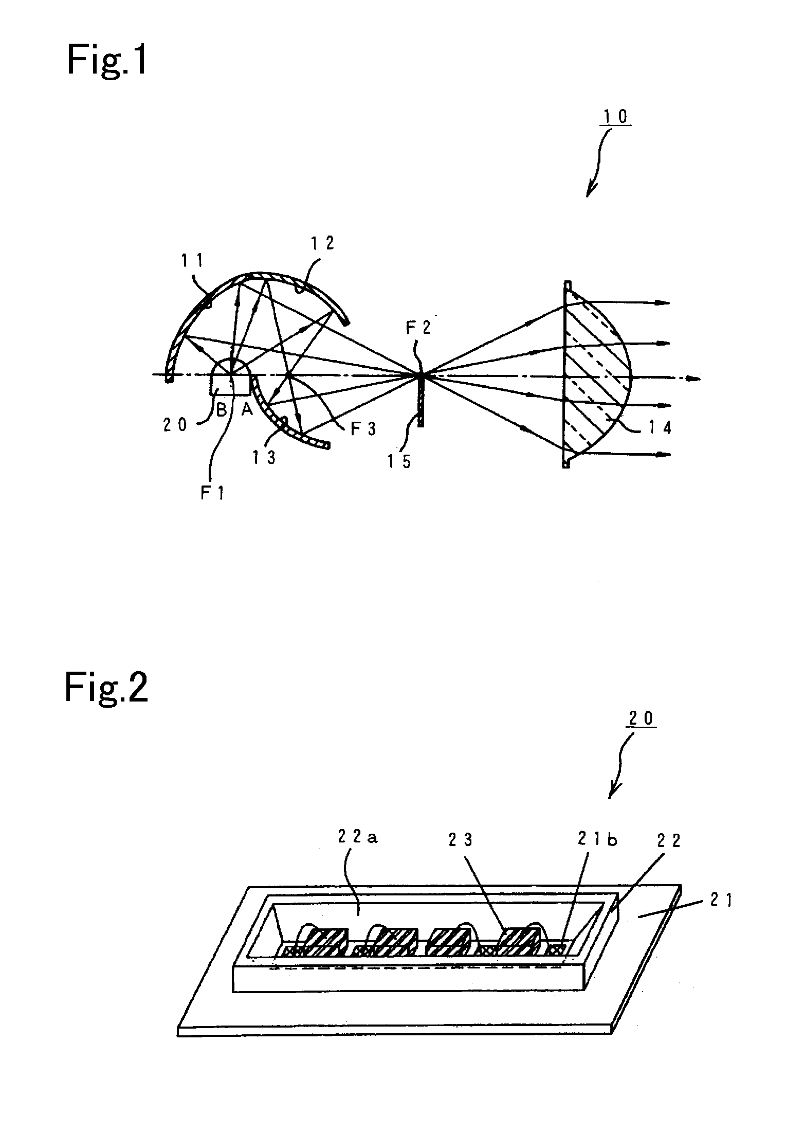
[0040] The disclosed subject matter will now be described in detail with reference to FIGS. 1 to 12. FIG. 1 is a schematic cross-section view showing a structure for an exemplary embodiment of a vehicle headlight made in accordance with principles of the disclosed subject matter. A vehicle headlight 10 shown in FIG. 1 is a projector-type headlight, which can include a light source 20, a first reflector 11, a second reflector 12, a third reflector 13, a projection lens 14, and a shield plate 15.

[0041] The first reflector 11 can have an elliptic surface that has a first focus F1 located near a central portion of the light source 20 so that a major axis thereof corresponds with a light axis in a direction towards light-emission for the light source 20. A second focus F2 can be located near a rearward focus of the projection lens 14. The first reflector can be configured to reflect light emitted from the light source 20 in a direction towards the projection lens 14. The second reflecto...


PUM


Abstract

The disclosed subject matter includes light sources that have a high luminous flux and a favorable bright distribution, and includes vehicle lamps that have both a favorable light distribution pattern and a capability of being miniaturized by using the LED light sources. The light source can include a base board, a reflector having a cavity with a slender rectangular opening, a plurality of semiconductor light emitting chips located in a line in the cavity, and an encapsulating resin in the cavity. At least one chip among the plurality of semiconductor light emitting chips can be located on a central bottom portion of the cavity. The cavity can have one slant angle in a direction of a short side that is smaller than another slant angle. The vehicle lamp can include the light source, a shield plate, an optical lens, and reflectors that are selected according to a kind and/or design of a vehicle lamp.

Description

[0001] This application claims the priority benefit under 35 U.S.C. §119 of Japanese Patent Application No. 2006-160672 filed on Jun. 9, 2006, which is hereby incorporated in its entirety by reference. BACKGROUND [0002] 1. Field [0003] The presently disclosed subject matter relates to a light source and a vehicle lamp, and more particularly to a light source device using a plurality of LED chips and to a vehicle lamp such as a headlight, auxiliary headlight, or other vehicle lamp using the light source device. [0004] 2. Description of the Related Art [0005] A conventional vehicle lamp that uses a plurality of LED chips for a light source is disclosed in patent document No. 1 (Japanese Patent Application Laid Open JP2005-276805). FIG. 13 of the present application is a schematic cross-section view of a lamp disclosed in patent document 1. The conventional vehicle lamp 1 is a projector-type headlight that includes: an LED light source 2; a first reflector 3a; a second reflector 3b; a ...

Claims


Application Information

Patent Timeline
IPC IPC(8): F21V1/00
CPCF21S48/1159F21S48/1388F21Y2101/02H01L25/0753H01L2224/48091Y10S362/80H01L2924/3025H01L2224/45144H01L2924/00H01L33/60F21Y2115/10F21S41/255F21S41/321F21S41/43F21S41/365F21S41/148H01L2924/00014
Inventor TACHIBANA, KAORI
Owner STANLEY ELECTRIC CO LTD
Why Eureka
Try Eureka