
Semiconductor light-emitting apparatus and vehicle headlight

a technology of semiconductors and headlights, applied in the direction of fixed installation, lighting and heating equipment, instruments, etc., can solve the problems of optical fiber, vehicle headlights may not provide the favorable light distribution pattern for drivers, and it is difficult to attach the light-emitting surface at the prescribed position, etc., to achieve a simple structure and favorable light distribution pattern

Active Publication Date: 2016-05-26
STANLEY ELECTRIC CO LTD
View PDF10 Cites 15 Cited by
  • Summary
  • Abstract
  • Description
  • Claims
  • Application Information

AI Technical Summary

Benefits of technology

The present patent text describes a new semiconductor light-emitting apparatus that can be used for vehicle lamps, general lighting, street lighting, and other applications. The apparatus includes an optical fiber and a wavelength converting layer that can emit various color lights, including a high-quality white light. The apparatus has excellent thermal resistance and radiation performance. Additionally, the patent describes a vehicle headlight that uses this reliable semiconductor light-emitting apparatus. The headlight has a simple structure and can provide a favorable light distribution even after long-term usage in a small sealed housing.

Problems solved by technology

Therefore, it may be difficult to attach the light-emitting surface at the prescribed position of the vehicle headlight along with the optical fiber, etc.
When a misalignment of the light-emitting surface occurs with respect to the prescribed position of the vehicle headlight, the vehicle headlight may not provide the favorable light distribution pattern for the drivers.

Method used


Image

  • Semiconductor light-emitting apparatus and vehicle headlight
  • Semiconductor light-emitting apparatus and vehicle headlight
  • Semiconductor light-emitting apparatus and vehicle headlight

Examples


Embodiment Construction

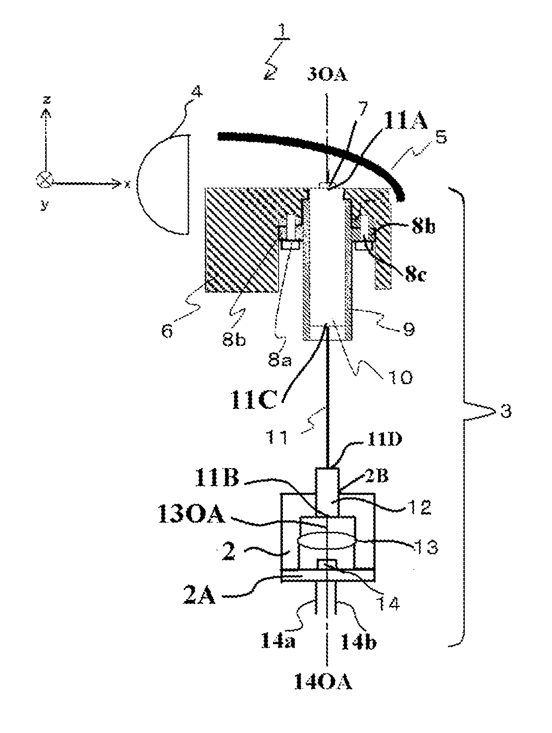
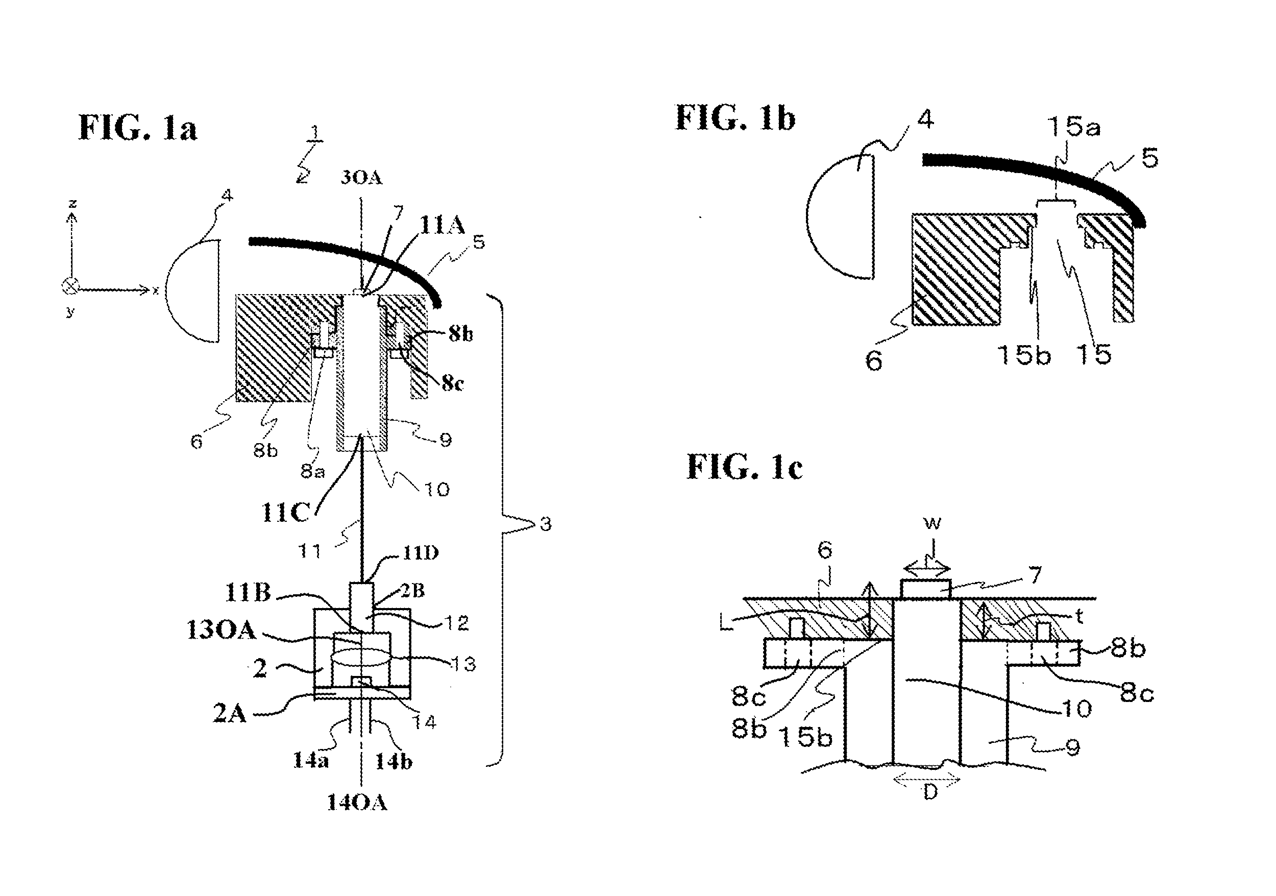
[0041]Exemplary embodiments and manufacturing methods of the disclosed subject matter will now be described in detail with reference to FIG. 1a to FIG. 12, in which the same or corresponding elements use the same reference marks. FIG. 1a is a schematic explanatory front cross-sectional view showing an exemplary embodiment of a vehicle headlight using a semiconductor light-emitting apparatus made in accordance with principles of the disclosed subject matter, FIG. 1b is a schematic explanatory front cross-sectional view showing a principal portion of the embodiment of the vehicle headlight shown in FIG. 1a without the semiconductor light-emitting apparatus, and FIG. 1c is a schematic enlarged front cross-sectional view showing an attaching portion of the semiconductor light-emitting apparatus to the vehicle headlight shown in FIG. 1a.

[0042]The vehicle headlight 1 can include: a semiconductor light-emitting apparatus 3 having a light-emitting optical axis 3OA configured to emit a mixt...


PUM

PropertyMeasurementUnit
light-emitting wavelengthaaaaaaaaaa
wavelengthaaaaaaaaaa

Abstract

A reliable semiconductor light-emitting apparatus including an optical fiber and a wavelength converting layer and a headlight using the semiconductor light-emitting apparatus can include a ferrule holder attaching the wavelength converting layer. The ferrule holder can also attach a first ferrule covering the optical fiber, which transmits light emitted from a semiconductor light-emitting chip toward the wavelength converting layer. When the light-emitting apparatus is used for the headlight, the apparatus can be easily incorporated into a prescribed position of the headlight with confidence via a lamp holder. Thus, the disclosed subject matter can provide reliable semiconductor light-emitting apparatuses having a high radiating efficiency that can emit various color lights including a substantially white color tone having favorable optical characteristics, which can be used for general lighting, a street light, stage lighting and the like, and which can be used for the headlight that can provide a favorable light distribution pattern.

Description

[0001]This application claims the priority benefit under 35 U.S.C. §119 of Japanese Patent Application No. 2014-238266 filed on Nov. 25, 2014, which is hereby incorporated in its entirety by reference.BACKGROUND[0002]1. Field[0003]The presently disclosed subject matter relates to semiconductor light-emitting apparatuses including an optical fiber, in which light emitted from a semiconductor light source is wavelength-converted by a wavelength converting layer, and to vehicle headlights using the semiconductor light-emitting apparatuses. More particularly, the disclosed subject matter relates to reliable semiconductor light-emitting apparatus having a high thermal conductivity and a high workability, which can be used for a vehicle lamp and the like, and to the vehicle headlights using such semiconductor light-emitting apparatuses.[0004]2. Description of the Related Art[0005]Semiconductor light-emitting devices, in which a part of light emitted from a semiconductor light-emitting chi...

Claims


Application Information

Patent Timeline
Patent Type & Authority Applications(United States)
IPC IPC(8): F21S8/10F21V9/16F21K99/00G02B6/42F21V8/00
CPCF21S48/1145G02B6/4206G02B6/0006F21Y2101/025F21K9/56F21V9/16G02B6/0008F21S41/192F21S41/198F21S41/24F21V9/30F21S41/176F21S41/16
Inventor SUZUKI, NAOTONOZAKI, TAKAHIKOWARAGAYA, TAKESHI
Owner STANLEY ELECTRIC CO LTD
Learn More