
Vehicle headlight

a headlight and headlamp technology, applied in the field of headlights of vehicles, can solve the problems of increased power consumption, complicated driver circuits, and difficult to achieve the above-described conventional headlights, and achieve the effect of high visual/visible quality and favorable light distribution patterns

Active Publication Date: 2012-08-28
STANLEY ELECTRIC CO LTD +1
View PDF14 Cites 18 Cited by
  • Summary
  • Abstract
  • Description
  • Claims
  • Application Information

AI Technical Summary

Benefits of technology

The present invention provides a projector headlight for a low beam that can conform to a light distribution standard for headlights and has a simple structure. The headlight includes a first optical unit, a second optical unit, and a third optical unit. Each optical unit includes an optical axis, a light source, and a projector lens. The projector lens has a light-emitting surface with a total reflection surface and a reflex surface. The light source is located adjacent to the light-emitting surface of the projector lens. The headlight can form various favorable light distribution patterns by changing the curvature factors of the light-emitting surface and the angles between the optical units. The vehicle lamp including the projector headlight can also form favorable light distribution patterns for a low beam and a high beam. The technical effects of the invention include improved low beam performance, reduced thickness, high brightness, and a wide range of light emission.

Problems solved by technology

On the other hand, because it is difficult to conform to a light distribution standard for a headlight using one LED chip, vehicle headlights using a plurality of LED optical units have been developed.
However, it is difficult for the above-described conventional headlights to form an elbow line and various cutoff lines for a low beam in their light distribution patterns.
However, the headlight may cause a problem such that power consumption may increase due to the many optical units.
However, the fifth conventional headlight may cause a problem in that the driver circuit may become complex.
Therefore, the structure may decrease the possible range of headlight design, and also may cause an unspectacular outside appearance.

Method used


Image

  • Vehicle headlight
  • Vehicle headlight
  • Vehicle headlight

Examples


Embodiment Construction

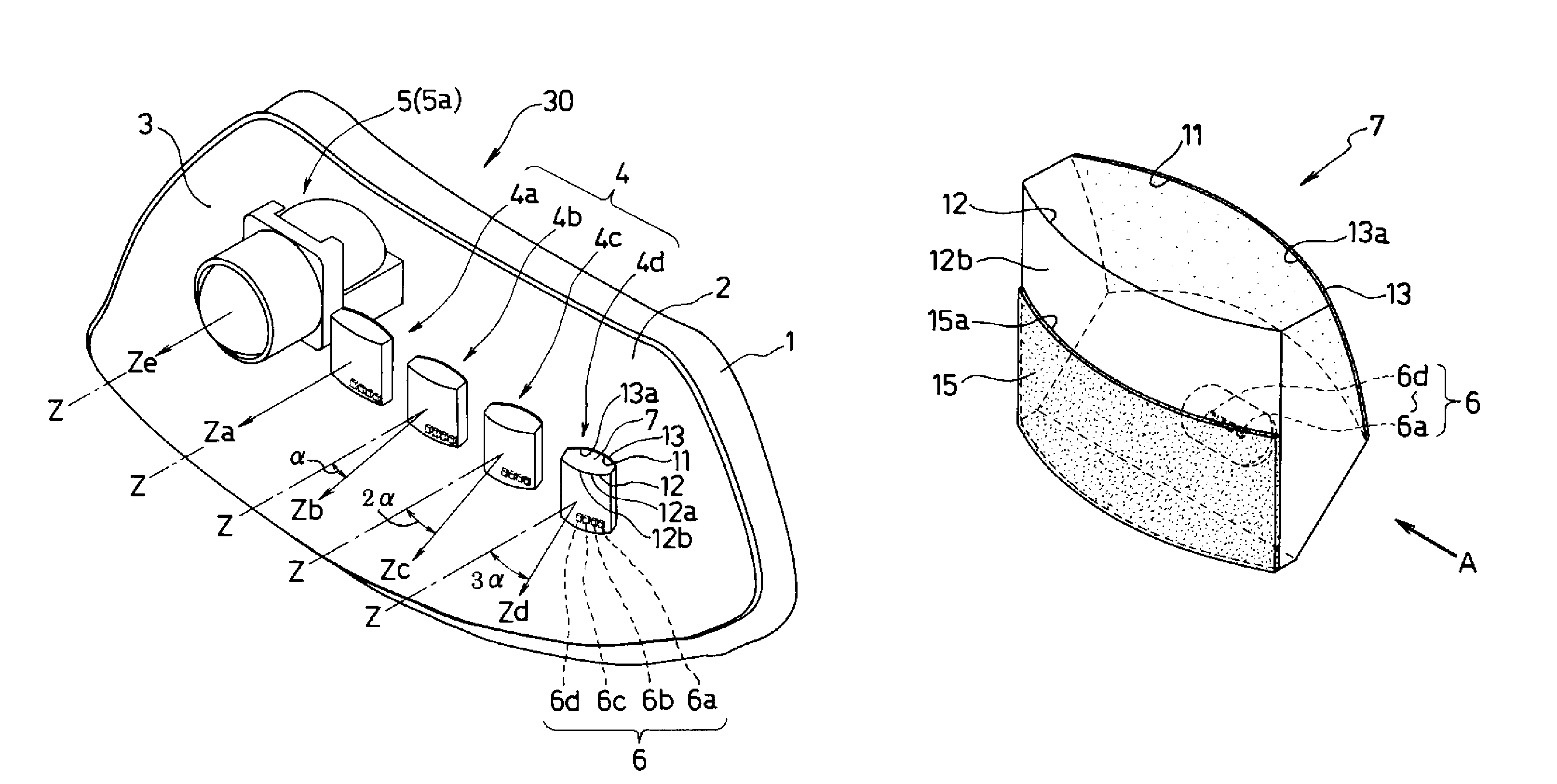
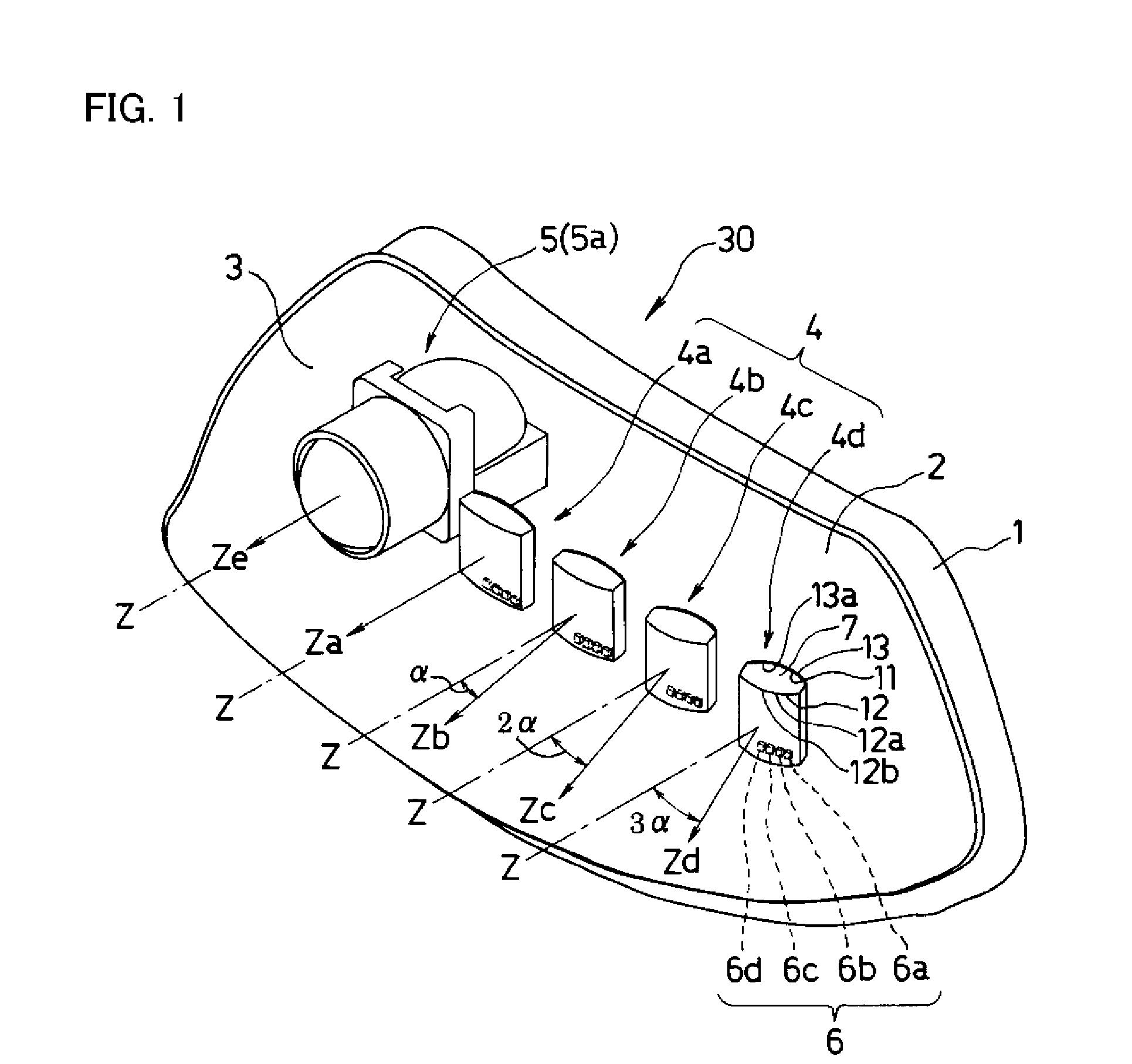
[0049]The disclosed subject matter will now be described in detail with reference to FIGS. 1 to 10, in which the same or corresponding elements use the same reference marks. FIG. 1 is a schematic perspective view showing an exemplary embodiment of a projector headlight made in accordance with principles of the disclosed subject matter. The projector headlight 30 is attached to the left side as viewed by a driver and constitutes one of a pair of left / right projector headlights of a vehicle that keeps to the left on a road.

[0050]The projector headlight 30 can include the following: a housing 1; a low beam projector lighting unit 4 located in the housing 1; a high beam projector lighting unit 5 located adjacent to the low beam projector lighting unit 4 in the housing 1; and an outer lens covering these projector lighting units 4 and 5 along with the housing 1. The low beam projector lighting unit 4 can be constructed from a first optical unit 4a, a second optical unit 4b, a third optic...


PUM


Abstract

The disclosed subject matter includes a projector headlight using a plurality of optical units for a low beam with a high visible / visual quality. Each of the optical units can include a plurality of LED devices and a projector lens. The projector lens can include a light-emitting surface including a reflex function and a reflex surface including a light incoming surface that is located on the opposite side of the light-emitting surface. The LED devices can be located adjacent the light incoming surface, and the optical units can be located so that angles between optical axes of adjacent optical units can become substantially a same angle. Thus, the projector headlight can form various favorable light distribution patterns by changing curvature factors of the light-emitting surface and the reflex surface of the projector lens in each of the optical units and by changing the angles between the optical axes of the adjacent optical units.

Description

[0001]This application claims the priority benefit under 35 U.S.C. §119 of Japanese Patent Application No. 2009-058188 filed on Mar. 11, 2009, which is hereby incorporated in its entirety by reference.BACKGROUND[0002]1. Field[0003]The presently disclosed subject matter relates to a vehicle headlight including a projector headlight using LED optical units for a low beam, and more particularly to a vehicle headlight including a projector headlight for a low beam having a favorable light distribution pattern and a high visual / visible quality.[0004]2. Description of the Related Art[0005]Recently, various vehicle headlights using LED optical units have been developed.[0006]This development has been brought about because LEDs have a long life and are battery friendly as compared with a light bulb, discharge lamp, etc. On the other hand, because it is difficult to conform to a light distribution standard for a headlight using one LED chip, vehicle headlights using a plurality of LED optica...

Claims


Application Information

Patent Timeline
Patent Type & Authority Patents(United States)
IPC IPC(8): F21S8/10
CPCF21S2/005F21S48/1154F21S48/1159F21S48/1195F21S48/1747F21W2101/10F21S41/147F21S41/663F21W2102/15F21S41/151F21W2102/155F21S41/148F21W2102/00
Inventor OHNO, MASAFUMIOWADA, RYOTAROMYOJIN, NORIKATSU
Owner STANLEY ELECTRIC CO LTD
Learn More