LED track lighting system

a lighting system and track technology, applied in the direction of lighting support devices, coupling device connections, lighting and heating apparatuses, etc., can solve the problems of high price of fluorescent tubes and incandescent tubes, and relatively short operating li

Inactive Publication Date: 2007-12-13
LEDTRONICS
View PDF20 Cites 83 Cited by
  • Summary
  • Abstract
  • Description
  • Claims
  • Application Information

AI Technical Summary

Problems solved by technology

For example, fluorescent (and incandescent) tube luminarie

Method used


Image

  • LED track lighting system
  • LED track lighting system
  • LED track lighting system

Examples


Embodiment Construction

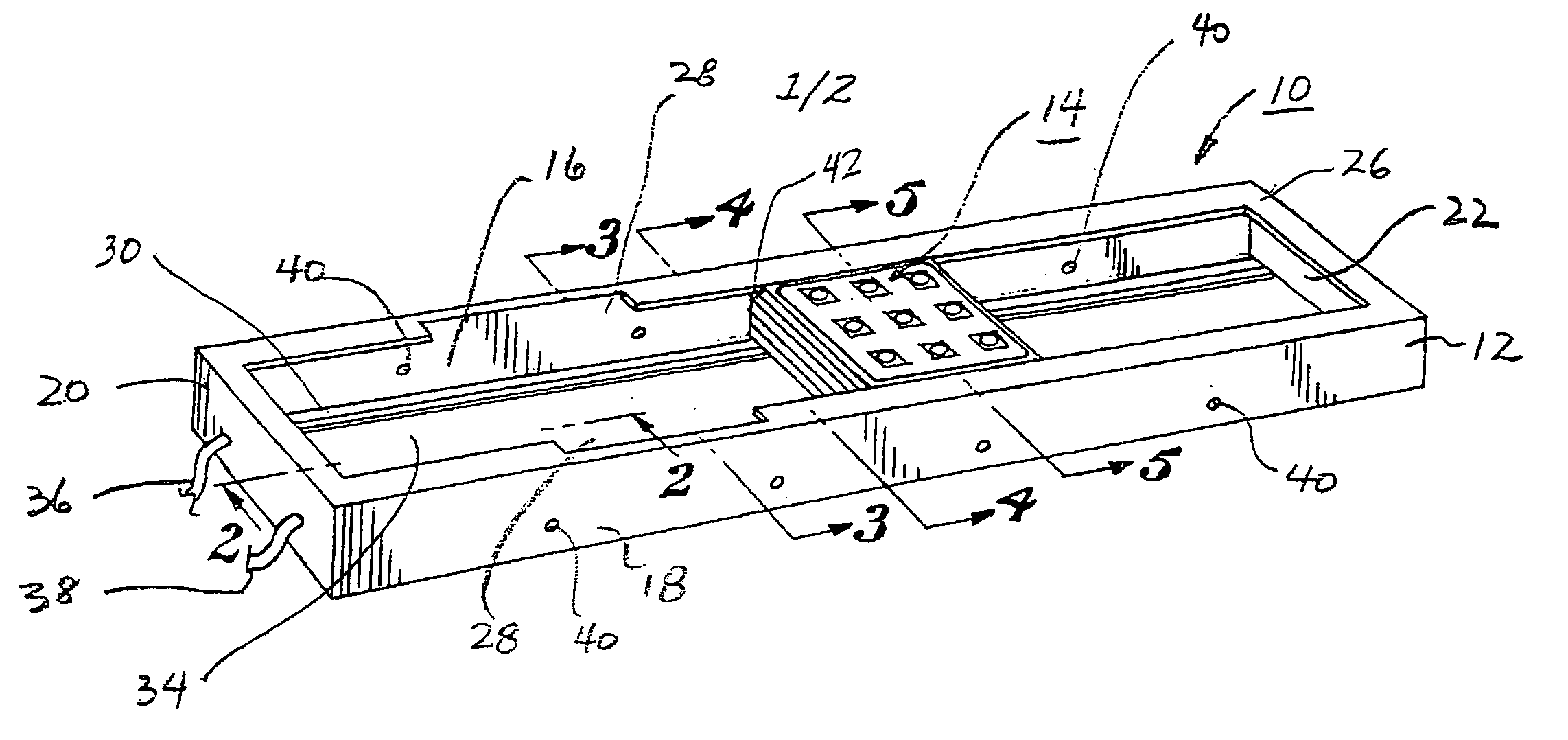
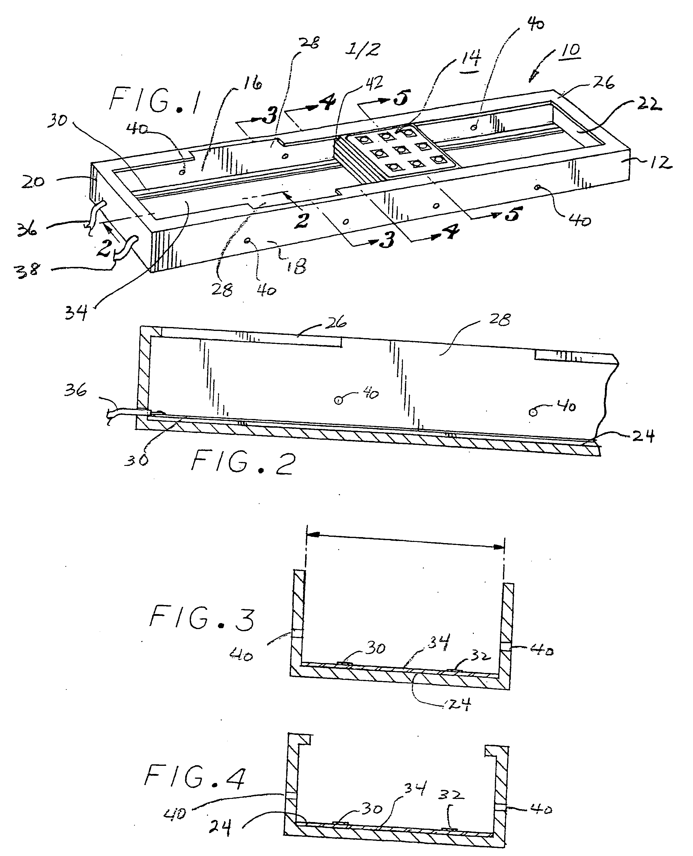
[0019]Referring now to FIG. 1, a perspective view of the LED track lighting system 10 of the present invention is illustrated. System 10 comprises a track, or rail, 12 having a LED module 14 positioned therewithin. Rail system 12 comprises a housing having side portions 16 and 18, ends 20 and 22 and bottom surface 24 (FIGS. 2-5). A lip portion 26 extends inwardly from the housing, lip portion 26 including a pair of indentations, or breaks, 28 formed therein to enable module 14 to be inserted within the track as will be explained hereinafter. Conductors, or bus bars, 30 and 32 are positioned on the top surface of a printed circuit board 34. A DC power source is coupled to wires 36 and 38, which in turn, are connected to bus bars 30 and 32, respectively thereby providing the lighting power to module 14.

[0020]As will be set forth in more detail hereinafter, housing side portions 16 and 18 include a plurality of spaced openings 40 adapted to receive locking detents.

[0021]Referring to FI...


PUM


Abstract

A track lighting system wherein a module having a plurality of LEDs mounted thereto is placed within a channel shaped rail system, the module being positionable within the rail system. A first surface of a first printed circuit board (PCB) is positioned on the bottom surface of the rail system and a pair of parallel conductive members are positioned on the second surface of the PCB. The bottom surface of the module has a plurality of spaced openings through which are inserted input power detents which contact corresponding conductive members. The power detents are connected to a circuit which converts the 24 VDC power input to a constant current; the output of the circuit being coupled to a second PCB upon which is mounted the LEDs. Openings are formed in the sides of the rail system and detents, positioned on the sides of the module, engage corresponding openings formed in the rail system sides to lock the module in position within the rail system.

Description

BACKGROUND OF THE INVENTION[0001]1. Field of the Invention[0002]The present invention provides a track lighting system having a slide-in LED module.[0003]2. Description of the Prior Art[0004]A track fixture is a light-producing luminaire with a fixture adapter mount and its electrical power connections. Power for the fixtures is provided from an electrical junction box main, connected to the track by an end-feed track-to-junction box connector. A number of depending track fixtures are positionable along the track and have luminaires that are mechanically and electrically connected to the track conductors with fixture mounting adapters. Line-voltage luminaries are connected to track conductors directly through a fixture adapter. Low-voltage luminaries are connected through a low-voltage power converter attached to a fixture adapter that is in turn mechanically and electrically connected to the track. Gas-discharge luminaries are connected through a ballast power converter attached to...

Claims


Application Information

Patent Timeline
IPC IPC(8): H01R33/00
CPCF21S8/038F21V21/35H01R25/142H01R13/7175F21Y2101/02F21Y2115/10H05K1/141H05K2201/041H05K2201/10106
Inventor LODHIE, PERVAIZSWEENEY, KEVIN T.
Owner LEDTRONICS
Why Eureka
Try Eureka