
Magnetic mixer drive system and method

a magnetic mixer and drive system technology, applied in the direction of mixing, mixing, chemistry apparatus and processes, etc., can solve the problems of system using bearings and seals not being the most suitable system, system can be difficult to clean, and canisters can provide a sor

Inactive Publication Date: 2007-12-13
SPX CORP
View PDF13 Cites 19 Cited by
  • Summary
  • Abstract
  • Description
  • Claims
  • Application Information

AI Technical Summary

Benefits of technology

"The patent text describes a magnetic drive mixer that overcomes problems of stagnant areas and reduced efficiency. The mixer has a containment shell with a driven outer magnetic rotor and an inner magnetic rotor with pitched blades. The inner magnetic rotor circulates fluid in the containment means. The method involves enclosing the entry opening with a containment shell and driving the outer magnetic rotor or an impeller shaft using the inner magnetic rotor. The invention has applications in mixing materials in a vessel."

Problems solved by technology

However, in situations where high sanitary and / or cleanability conditions are required, the system using bearings and seals may not be the most suitable system.
That is, these systems can be difficult to clean and / or the bearing and seal regions may tend to collect undesirable materials.
However, one disadvantage of some side entry mixers in some applications is that the canister can provide a sort of “dead zone” where a lack of circulation of the fluid or other material being mixed occurred.
In some applications, such a lack of circulation or dead zone is disadvantageous, particularly in the case of very long cycle times between cleanings, for example, if the material is biological or bioactive, food or cosmetic related, or otherwise susceptible to spoilage or degredation, the stagnation can lead to problems with the product.
For example, in the case of food products, it may be undesirable to have a stagnant area inside the canister region because spoilage or similar degradation of the food product could occur.

Method used


Image

  • Magnetic mixer drive system and method
  • Magnetic mixer drive system and method
  • Magnetic mixer drive system and method

Examples


Embodiment Construction

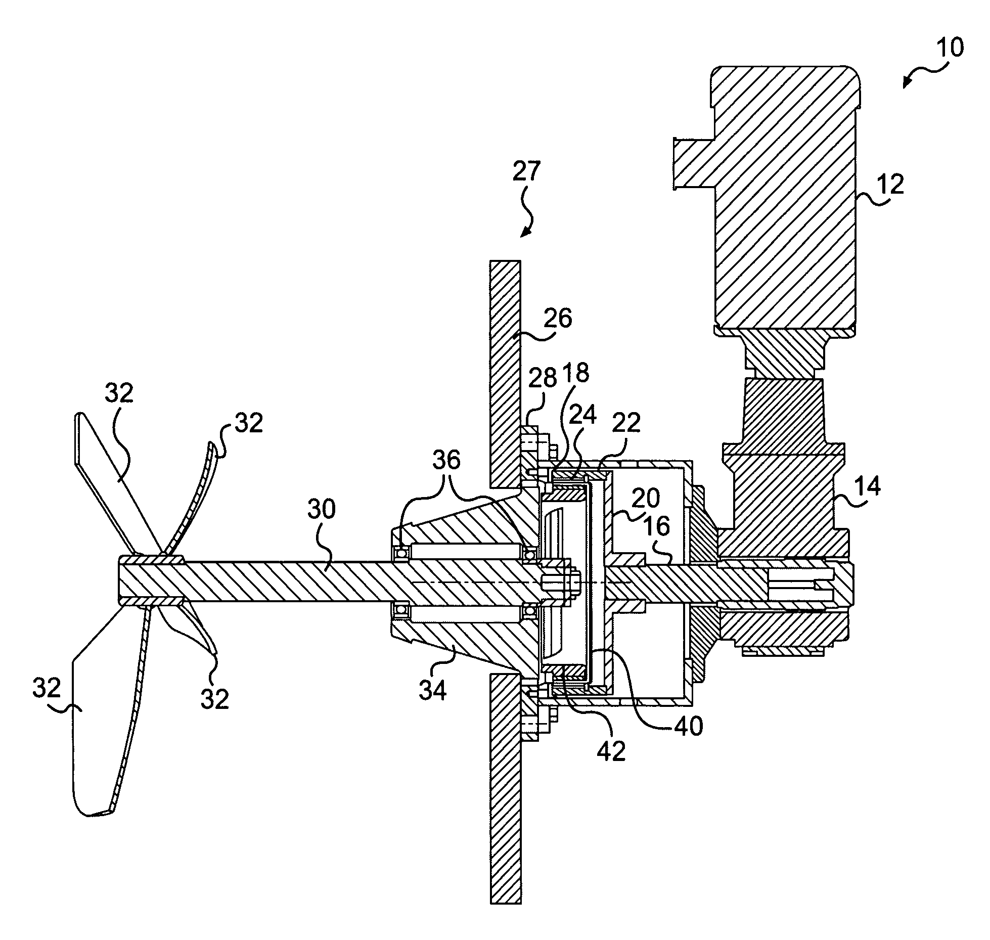
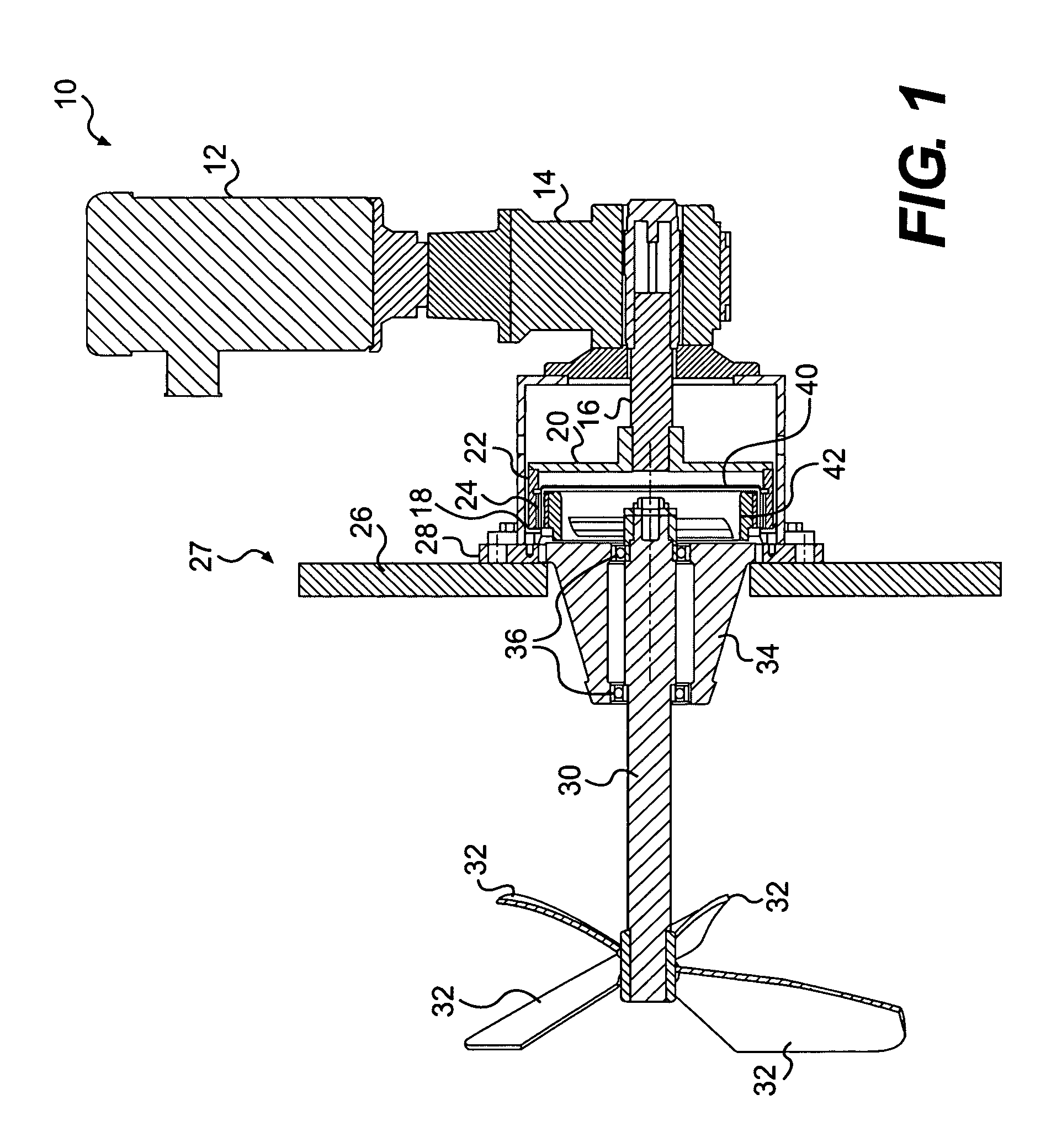
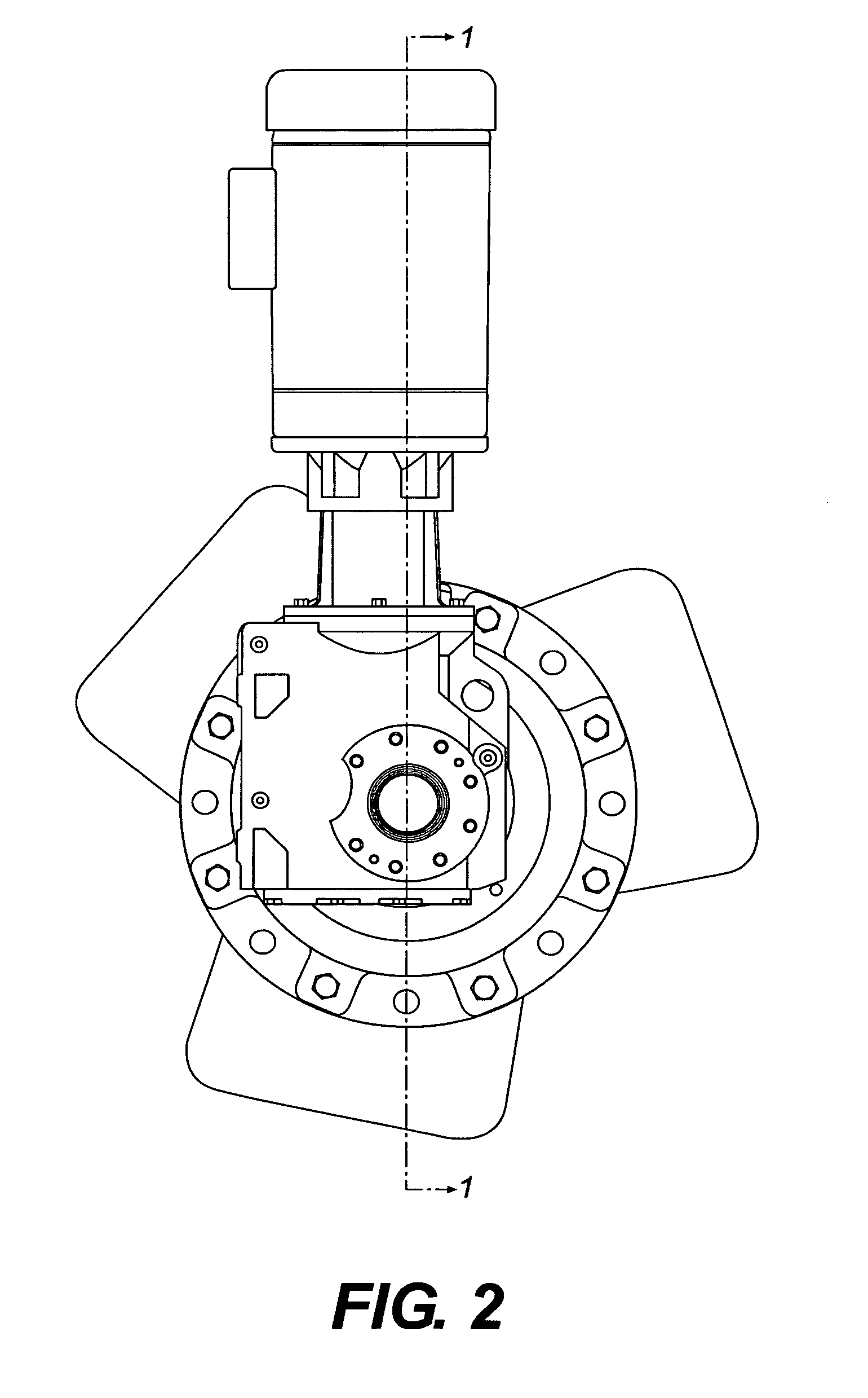
[0021]Some preferred embodiments provide a method and apparatus for magnetic mixing that avoids stagnation in the area inside the canister or containment shell and in the area of the inner magnetic motor. The references to canister and containment shell herein refer to like parts. Some preferred embodiments of the invention will now be described with reference to the drawing figures, in which like reference numerals refer to like components throughout.

[0022]FIG. 1 is a cross-sectional view of a magnetic impeller drive system 10 according to one preferred embodiment of the present invention. The system 10 includes a motor 12, which is typically an electrically driven motor, that is connected to a gear box system 14, which typically includes a gear reducer having a predetermined ratio.

[0023]The gear box 14 drives a drive shaft 16 which is connected to an outer magnetic rotor 18. The outer magnetic rotor 18 can include a radial disc 20 which is connected to a ring-shaped outer magnetic...


PUM


Abstract

An improved magnetic drive for a mixing system and method, wherein stagnation or collection of material in the region of the containment shell and any magnetic rotor are alleviated by the provision of pitched blades provided as radially extending spokes in the inner magnetic rotor. This bladed rotor design may be particularly advantageous in the case of a side entry mixer.

Description

FIELD OF THE INVENTION[0001]The present invention relates generally to the field of mixers, mixing devices and mixing methods and, more particularly, relates to the field of mixers wherein a rotating shaft supports a rotating impeller inside a vessel, and the shaft is magnetically driven.BACKGROUND OF THE INVENTION[0002]Mixers and mixing devices are in wide use in industry. One type of mixing device mixes a material inside of a vessel by virtue of a shaft that projects into the vessel and is rotated by a drive system. The shaft supports radially extending impellers, which rotate with the shaft and agitate, mix, and otherwise impart energy to the material in the vessel.[0003]Usually the drive system, which includes a motor and a gear box, is located outside of the vessel. Thus, the mixing impeller shaft, which is disposed inside the vessel, needs to be driven by this drive system, which is outside of the vessel. In one arrangement, the shaft penetrates an aperture of the vessel and i...

Claims


Application Information

Patent Timeline
Patent Type & Authority Applications(United States)
IPC IPC(8): B01F13/08
CPCB01F7/002B01F13/0827B01F7/06B01F27/09B01F27/71B01F33/4534B01F33/453
Inventor MARKLE, STEPHEN L.
Owner SPX CORP
Learn More