
Cable Mount for Cable Trays

a cable tray and cable tie technology, applied in the field of cable tray mounts, can solve the problem of difficult to route the cable tie back through the second slot of the cable tray

Inactive Publication Date: 2007-12-20
PANDUIT
View PDF27 Cites 30 Cited by
  • Summary
  • Abstract
  • Description
  • Claims
  • Application Information

AI Technical Summary

Problems solved by technology

However, after routing the cable tie through the first slot in the cable tray, it is sometimes difficult to route the cable tie back through the second slot in the cable tray.

Method used


Image

  • Cable Mount for Cable Trays
  • Cable Mount for Cable Trays
  • Cable Mount for Cable Trays

Examples


Embodiment Construction

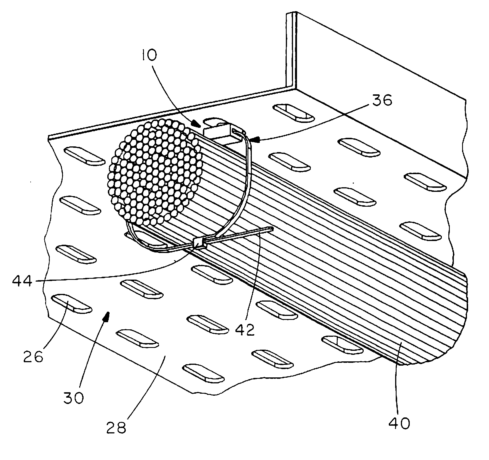
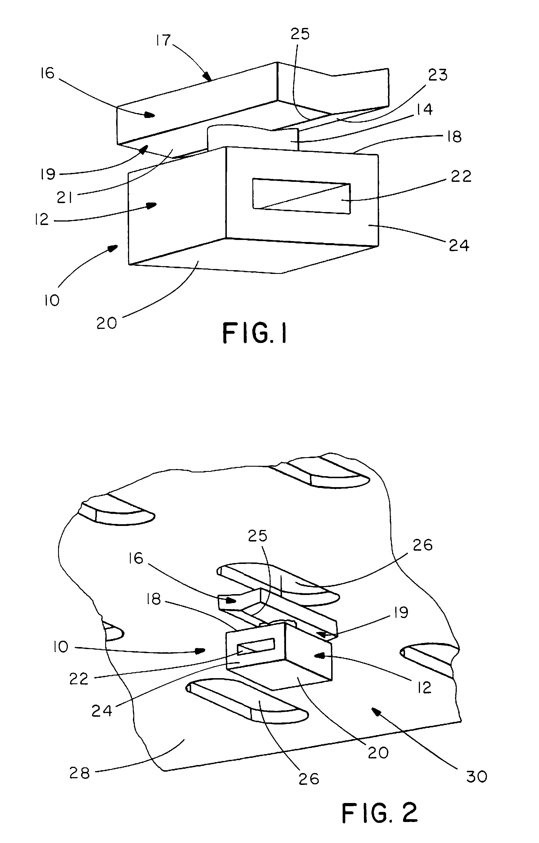
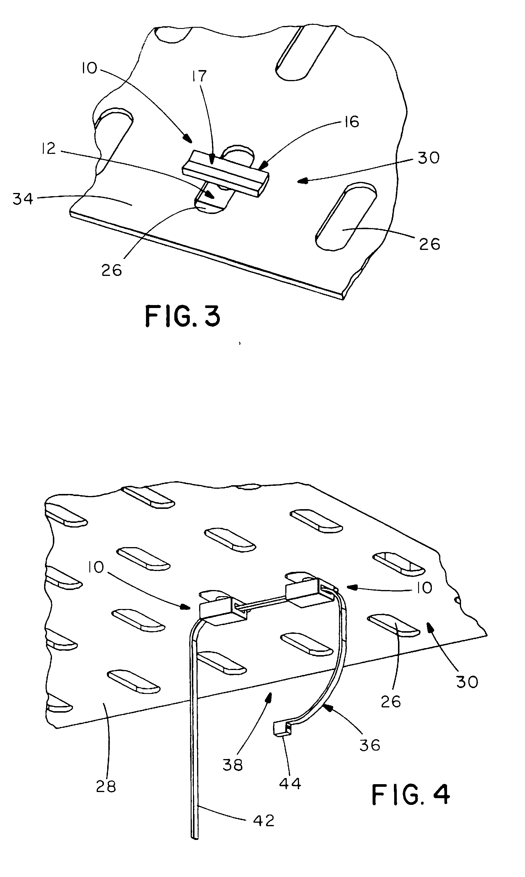
[0014]Referring to FIG. 1, one embodiment of the cable mount 10 of the present invention is shown. Cable mount 10 includes base 12, shaft 14, and head 16. Cable mount 10 may be used to secure cable running along the top or bottom of a cable tray. Cable mount 10 is preferably constructed of plastic, but may comprise a variety of other materials, including various types of metal. Cable mount 10 may be injection molded.

[0015]Referring to FIGS. 2 and 3, cable mount 10 may comprise a beveled head 16. Head 16 may comprise top surface 17 and bottom surface 19. One or both of top and bottom surface 17 and 19 may comprise beveled or angled portion, defined by first surface 21 and second surface 23 intersecting at apex 25 and forming an obtuse angle. Although head 16 is shown in the shape of a rectangle, head may take other shapes, such as triangular and round.

[0016]Head 16 is sized and shaped to pass through an opening in a cable tray. Securement of head 16 to cable tray is accomplished by p...


PUM


Abstract

A cable mount for carrying a bundle of cables comprises a base comprising a slot for receipt of a cable tie, a shaft connected to the base and a head connected to the shaft, the head for securing the cable mount to a cable tray through an opening. The cable mount may be secured to the tray by rotating the mount less than 180 degrees such that a length of the head of the cable mount is transverse to a length of the opening in the cable tray. The cable mount is easy to use and may be installed without the use of tools.

Description

[0001]This application claims the benefit of U.S. Provisional Application No. 60 / 804,880 filed Jun. 15, 2006, which is hereby incorporated by reference in its entirety.FIELD OF INVENTION [0002]This invention relates to cable mounts and, more particularly, to cable mounts for supporting bundles of cables running along the top and / or bottom of cable trays.BACKGROUND [0003]Typically, a cable tie is routed through the elongated slots of a cable tray, and then the cable tie secures a bundle of cables. However, after routing the cable tie through the first slot in the cable tray, it is sometimes difficult to route the cable tie back through the second slot in the cable tray.[0004]It would be desirable to provide a cable mount that makes it easier to support bundles of cables running along the top and / or bottom of a cable tray.SUMMARY OF THE INVENTION [0005]The present invention relates to an improved cable mount for carrying a bundle of cables on a cable tray, the cable mount comprising a...

Claims


Application Information

Patent Timeline
Patent Type & Authority Applications(United States)
IPC IPC(8): F16L3/12
CPCH02G3/0437F16L3/137H02G3/32
Inventor CAVENEY, JACK E.
Owner PANDUIT
Learn More