
Separable loadbreak connector and system

Inactive Publication Date: 2007-12-20
COOPER TECH CO
View PDF99 Cites 25 Cited by
  • Summary
  • Abstract
  • Description
  • Claims
  • Application Information

AI Technical Summary

Problems solved by technology

Such variety of component pieces makes repair or replacement of the components laborious in that each piece is generally custom made and assembled.
However, SF6 gas is difficult to contain, air requirements excessive spacing between energized parts to be an effective insulator, and oil is also difficult to contain and is a fire hazard.
However, if the abutting joint is not abutted and securely bonded, a gap between the insulative sheath and the insulative layer permits shorting the flashover distance between the energized contact extension and ground potential at an opening end of interface.

Method used


Image

  • Separable loadbreak connector and system
  • Separable loadbreak connector and system
  • Separable loadbreak connector and system

Examples


Embodiment Construction

[0018] The following detailed description illustrates the invention by way of example and not by way of limitation. The description clearly enables one skilled in the art to make and use the invention, describes several embodiments, adaptations, variations, alternatives, and uses of the invention, including what is presently believed to be the best mode of carrying out the invention.

I. Introduction To the Invention

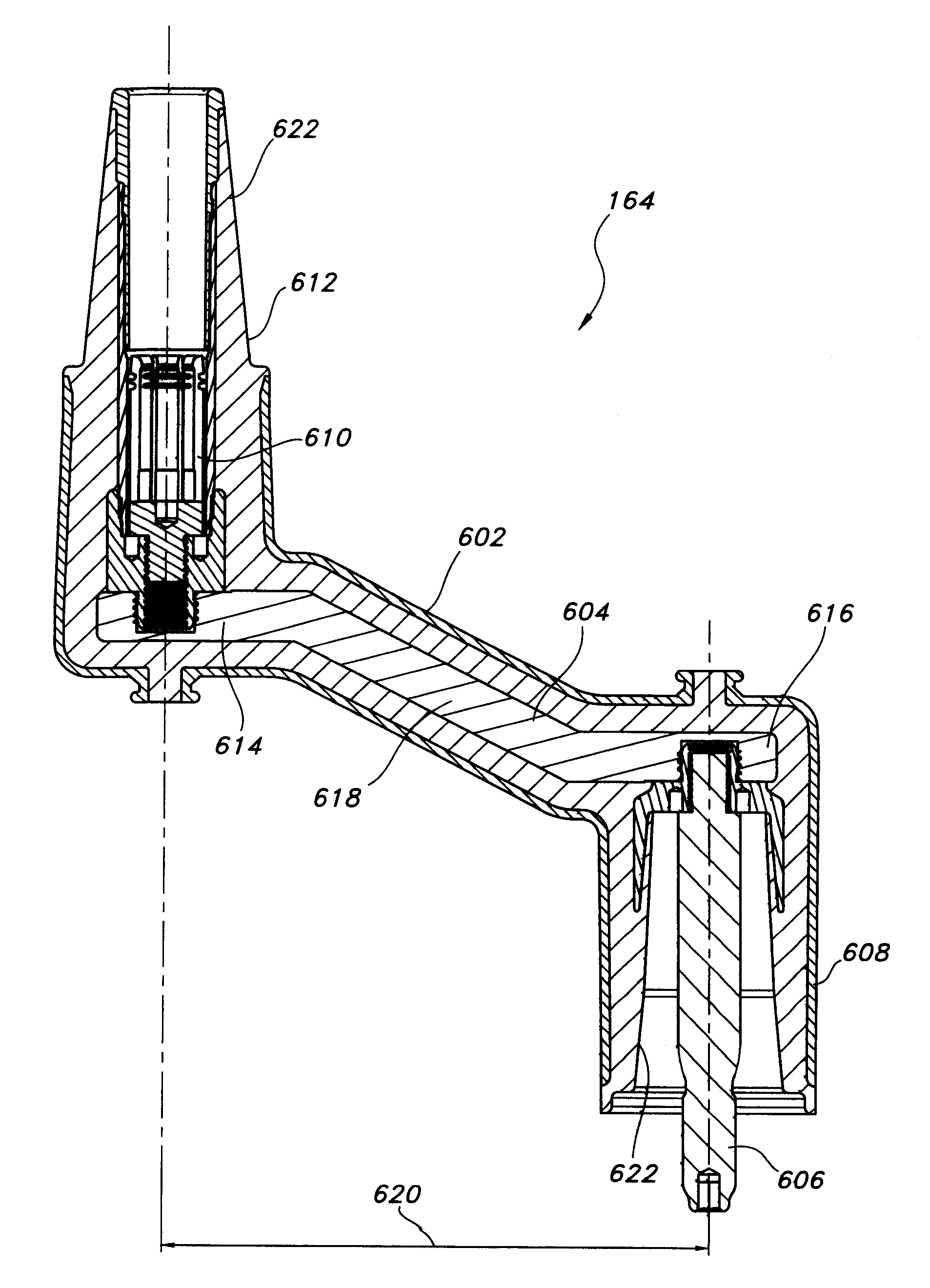
[0019] High-voltage separable connectors interconnect sources of energy such as transformers to distribution networks or the like. Frequently, it is necessary to connect and disconnect the electrical connectors. These connectors typically feature an elbow component, which contains a male connector, and a bushing component, which contains a female connector. When the components are connected, elastomeric O-rings seal the connection.

[0020] Disconnecting energized connectors is an operation known as a loadbreak. A problem known as “flashover” has been known to occur while ...


PUM

PropertyMeasurementUnit
Timeaaaaaaaaaa
Angleaaaaaaaaaa
Electrical conductoraaaaaaaaaa

Abstract

Separable loadbreak connectors include an overlapping insulation joint and interchangeable preconfigured connector assemblies.

Description

CROSS REFERENCE TO RELATED APPLICATIONS [0001] This application is a continuation-in-part application of U.S. application Ser. No. 11 / 273,192 filed Nov. 14, 2005, the disclosure of which is hereby incorporated by reference in its entirety.BACKGROUND OF THE INVENTION [0002] This invention relates generally to bus systems and cable connectors for electric power systems, and more particularly to separable insulated loadbreak connector systems for use with modular bus systems. [0003] Electrical power is typically transmitted from substations through cables which interconnect other cables and electrical apparatus in a power distribution network. The cables are typically terminated on bushings that may pass through walls of metal encased equipment such as capacitors, transformers or switchgear. [0004] Separable loadbreak connectors allow connection or disconnection of the cables to the electrical apparatus for service, repair, or expansion of an electrical distribution system. Such connec...

Claims


Application Information

Patent Timeline
IPC IPC(8): H01R13/53
CPCH01H33/66207H01H33/666Y10T29/49204H01H2033/6665H02B13/0358H01H2033/6623
Inventor HUGHES, DAVID CHARLESSTEINBRECHER, BRIAN TODD
Owner COOPER TECH CO
Features
  • Generate Ideas
  • Intellectual Property
  • Life Sciences
  • Materials
  • Tech Scout
  • Unparalleled Data Quality
  • Higher Quality Content
  • 60% Fewer Hallucinations
Learn More