Dust suction device

a technology filter surface, which is applied in the field of dust suction device, can solve the problems of increasing manufacturing costs, requiring relatively extensive additional installation space for pipes, and applying dust suction devices, and achieves the effect of simple cleaning of filter surfa

a technology filter surface, which is applied in the field of dust suction device, can solve the problems of increasing manufacturing costs, requiring relatively extensive additional installation space for pipes, and applying dust suction devices, and achieves the effect of simple cleaning of filter surfa

US20070294857A1Inactive Publication Date: 2007-12-27HILTI AG

Image

  • Dust suction device
  • Dust suction device
  • Dust suction device

Examples


Embodiment Construction

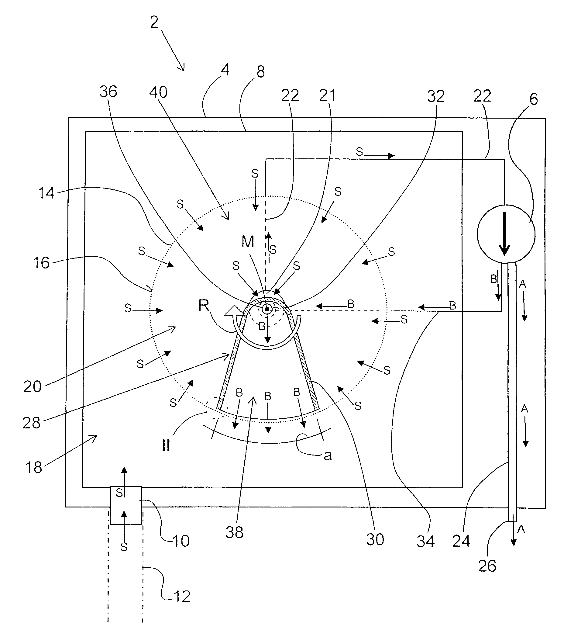
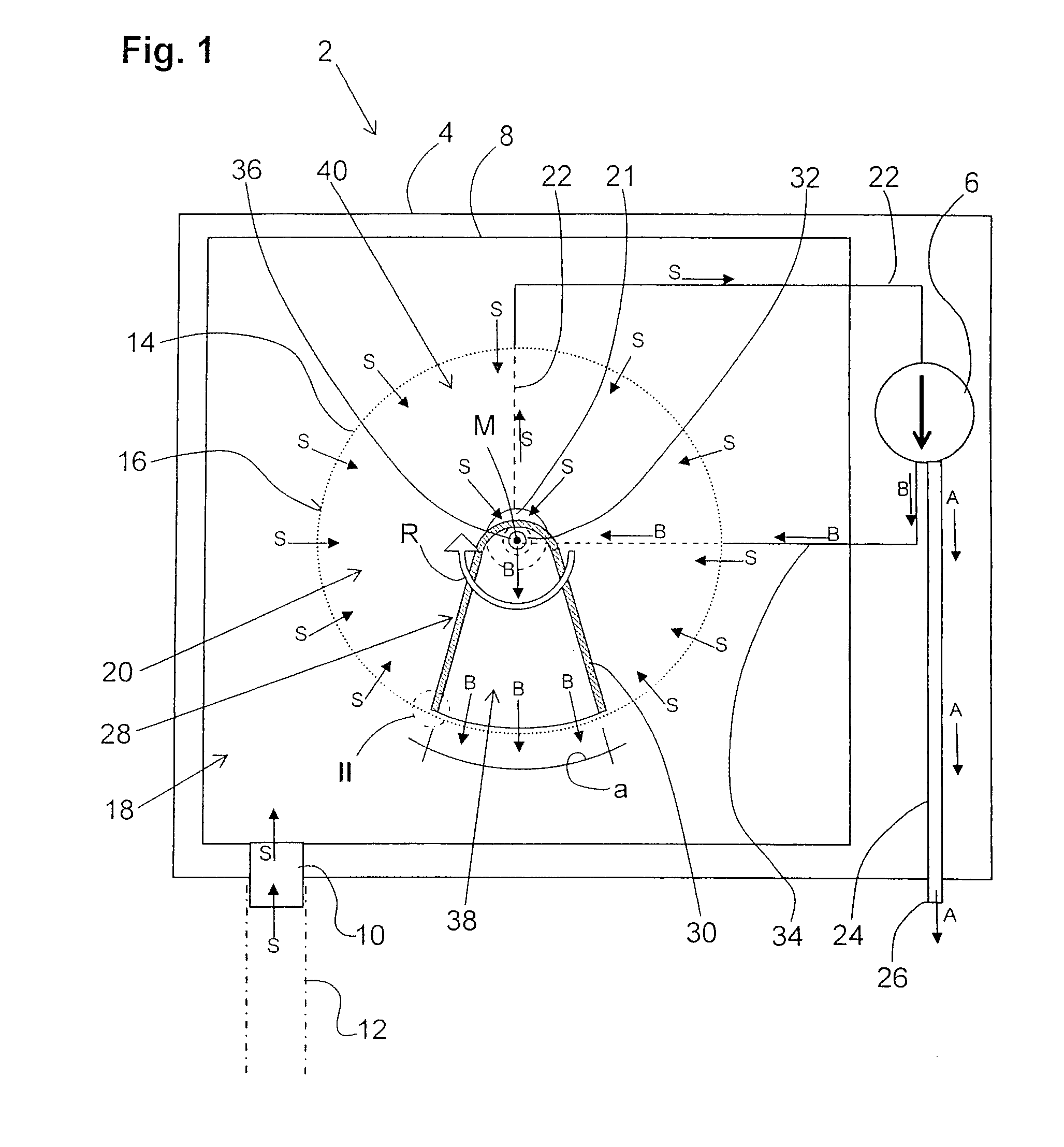
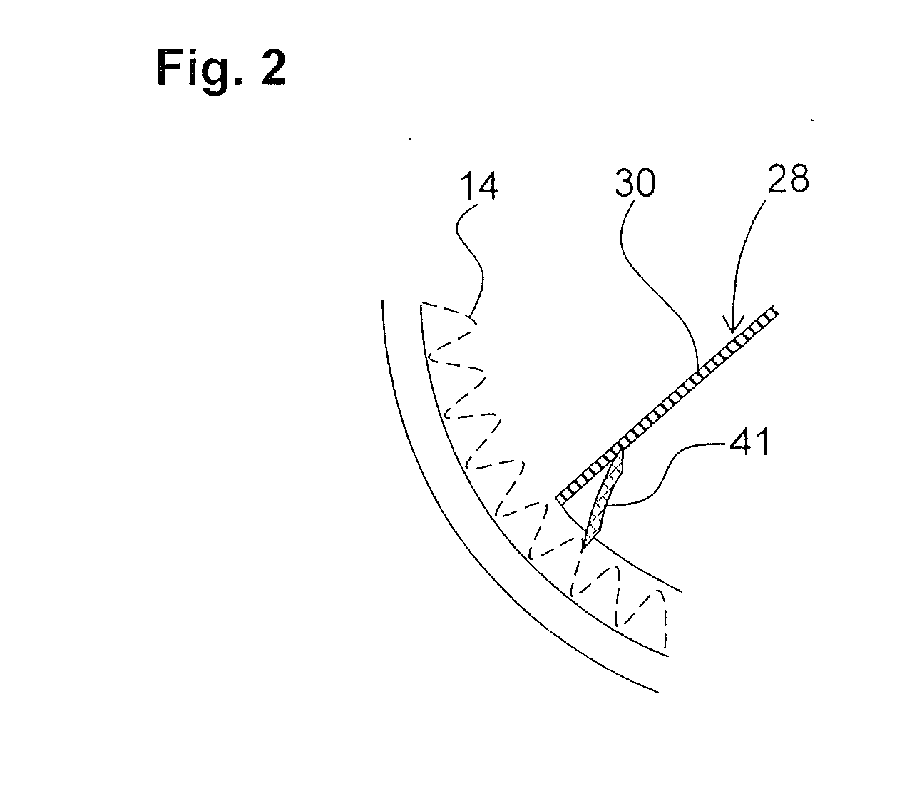
[0024]FIG. 1 shows a basic schematic view of a dust suction device 2 in the form of an industrial vacuum cleaner. It has a blower device 8 in a main housing 4 and has an inner housing 8. Further, an intake connection piece 10 is provided at the main housing 4 to which, for example, a pipe-shaped or hose-shaped suction element 12 can be connected and which opens into the inner housing 8.

[0025]A filter element 14 having a substantially cylindrical filter surface 16 is held in the inner housing 8. The filter element 14 serves to separate dust and dirt particles from an intake flow, indicated by arrows S, which is generated by the blower device 6 at the suction element 12. The intake flow S flows from the suction element 12 via the intake connection piece 10 into the inner housing 8 and through the filter surface 16 into the interior of the filter element 14. The inner housing 8 forms a collecting chamber 18 for the retained dust and the dirt particles, this collecting chamber 18 being ...


PUM

PropertyMeasurementUnit
angleaaaaaaaaaa
covering angleaaaaaaaaaa
displacementaaaaaaaaaa

Abstract

A dust suction device (2), particularly in the form of an industrial vacuum cleaner, has a blower device (6) for generating an intake flow (S), a filter surface (16) for separating dust and dirt particles from the intake flow (S), a collecting chamber (18) for collecting the dust and the dirt particles which is located upstream of the filter surface (16) with respect to the intake flow (S), a clean air chamber (20) which is arranged downstream of the filter surface (16) and is separated from the collecting chamber (18) by the filter surface (16), with the filter surface (16) being acted upon in some areas by a cleaning flow of the blower device (6) which flows through the filter surface (16) in the direction opposite the direction of the intake flow (S), and an adjustable dividing wall (30) provided in the clean air chamber (20) and separating a vacuum area (40) that can be generated by the blower device (6) from an overpressure area (38) that can likewise be generated by the blower device (6).

Description

BACKGROUND OF THE INVENTION[0001]1. Field of the Invention[0002]The invention related to a dust suction device, particularly in the form of an industrial vacuum cleaner, with a blower device for generating an intake flow. Further, the dust suction device has a filter surface for separating dust and dirt particles from the intake flow. A collecting chamber for collecting the dust and the dirt particles is arranged downstream of the blower device, in the direction of the intake flow and upstream of the filter surface, and a clean air chamber is arranged downstream of the filter surface and is separated from the collecting chamber by the filter surface. The filter surface can be acted upon in some areas by a cleaning flow of the blower which flows through the filter surface in the direction opposite the intake flow direction for cleaning by back-blowing.[0003]2. Description of the Prior Art[0004]In devices of the type mentioned above, the filter surface can be back-flushed by the clean...

Claims


Application Information

Patent Timeline
27 Dec 2007
Publication
US20070294857A1
IPC
A47L9/20
CPC
B01D2273/28; B01D46/0071; Y02A50/2351; B01D46/72
Inventors
HEINRICHS, VIKTOR