Crimp terminal with seal member

a technology of sealing member and clamping terminal, which is applied in the direction of connection contact member material, connection insulation, coupling device connection, etc., can solve the problems of narrow seal member range and often accompanied by manufacturing difficulties, so as to alleviate manufacturing difficulties, reduce manufacturing difficulties, and reduce manufacturing difficulties

Active Publication Date: 2020-02-25
YAZAKI CORP
View PDF21 Cites 3 Cited by
  • Summary
  • Abstract
  • Description
  • Claims
  • Application Information

AI Technical Summary

Benefits of technology

In the crimp terminal of the present invention, by crimping, each edge of the recesses provided on the inner surface of the barrel portion bites into the aluminum core wire, whereby good conduction between the covered electric wire and the crimp terminal can be obtained. The plurality of recesses provided on the inner surface of the barrel portion partially overlaps the seal member for securing waterproofness against the contact portion with the aluminum core wire. Therefore, the recess at the position overlapping with the seal member can be used as a mark when the seal member is provided on the inner surface of the barrel portion, and it is possible to alleviate the difficulty in manufacturing at this point. In addition, the recesses overlapping with the seal member suppress a movement of the seal member due to a pressure applied at the time of crimping, and also contribute to securing the waterproofness at a higher level. As described above, according to the crimp terminal of the present invention, a part of the recesses provided for good conduction between the covered electric wire and the crimp terminal is used while securing waterproofness against the contact portion with the aluminum core wire, allowing for alleviating difficulties in manufacturing.
According to this preferred crimp terminal, the inner surface shape of the barrel portion is simplified such that the plurality of recesses is dispersed over substantially the entire area, so that it is possible to alleviate difficulty in manufacturing. In addition, when the seal member is provided, providing along the outer periphery of the barrel portion allows the seal member and the recess to overlap even if the seal member is somewhat inclined or the like. That is, since a high positional accuracy is unnecessary when providing the seal member, it is possible to further alleviate difficulties in manufacturing even in this respect.
According to this crimp terminal of the reference example, the movement of the seal member due to the pressure applied at the time of crimping is also suppressed by the groove portion overlapping with the seal member. Therefore, according to this crimp terminal of the reference example, it is possible to alleviate difficulties in manufacturing while securing waterproofness at a higher level. In addition, the groove portion overlapping the seal member can also be used as a marker for providing the seal member on the inner surface of the barrel portion, allowing for further alleviating manufacturing difficulty in this point.
According to the present invention, it is possible to obtain a crimp terminal in which difficulty in manufacturing is alleviated while ensuring waterproofness against the contact portion with the aluminum core wire.

Problems solved by technology

However, with the conventional crimp terminal as shown by way of example in FIG. 49, since it is just a small size for attachment to a covered electric wire, and an installation range of the seal member is narrow, manufacturing is often accompanied by difficulties.

Method used


Image

  • Crimp terminal with seal member
  • Crimp terminal with seal member
  • Crimp terminal with seal member

Examples


Embodiment Construction

Hereinafter, various embodiments of the present invention will be described. First, a reference example will appropriately be explained with modifications.

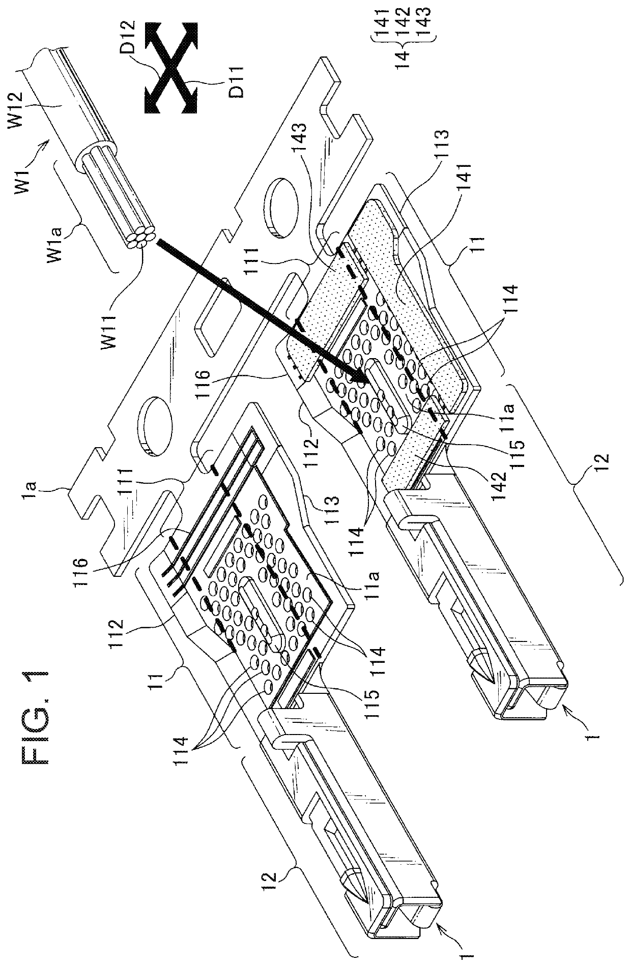
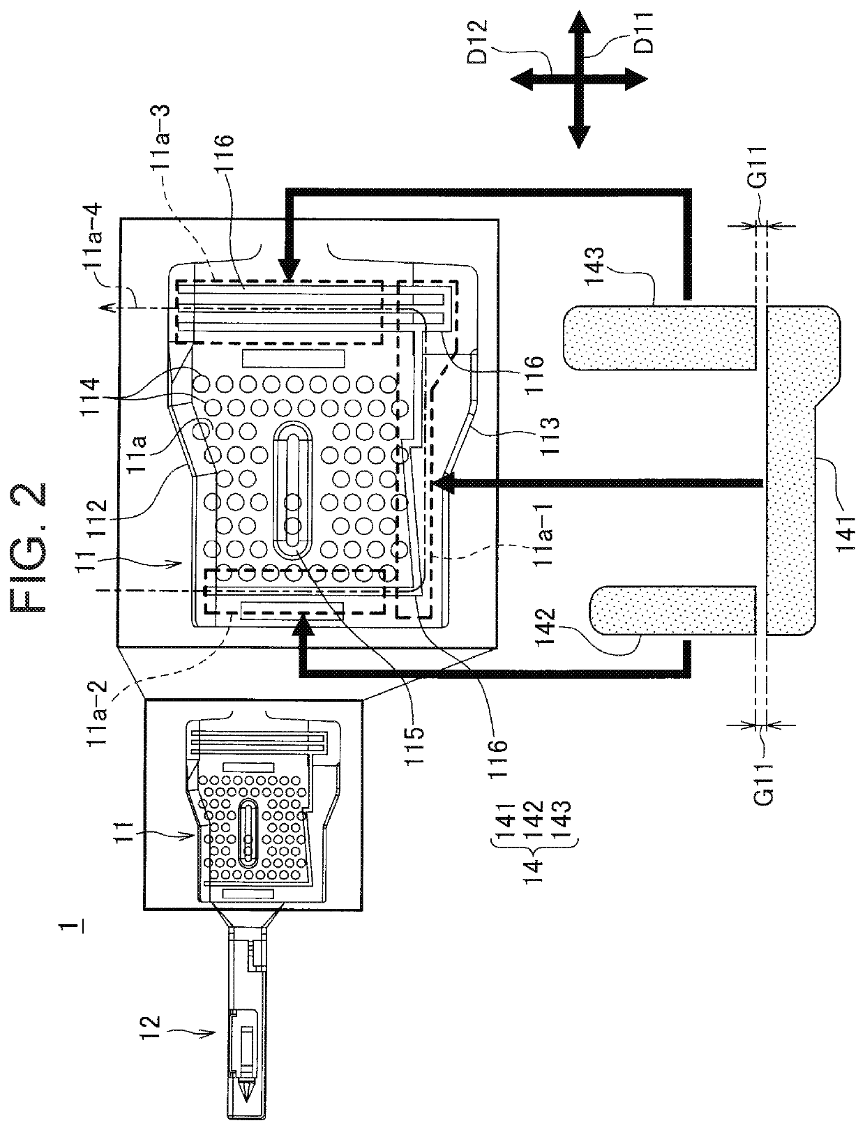
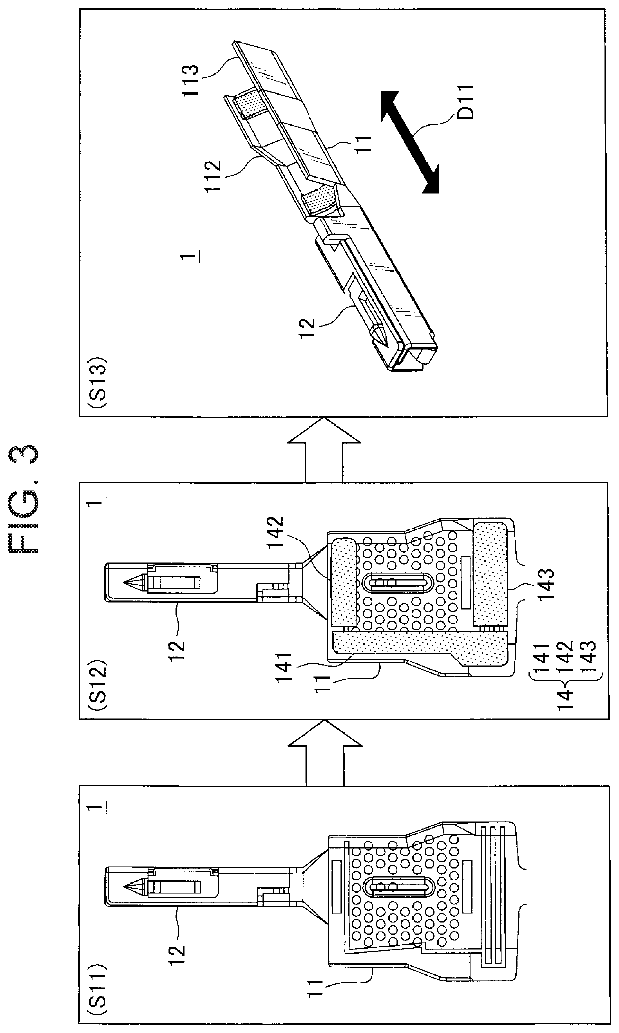
FIG. 1 is a view for explaining a crimp terminal according to a reference example of the present invention.

The crimp terminal 1 according to the reference example is crimped to an end portion W1a of a covered electric wire W1 where an aluminum core wire W11 is exposed. The crimp terminal 1 includes a barrel portion 11, a terminal portion 12, and a seal member 14. Although two crimp terminals 1 are shown in FIG. 1, one crimp terminal 1 is shown with the seal member 14 removed so that the inner surface shape of the barrel portion 11 can be visually observed.

The barrel portion 11 and the terminal part 12 are made by punching and sheet metal working from a metal plate such as a copper alloy, and the surface is subjected to tin plating or gold plating. The barrel portion 11 and the terminal portion 12 are arranged in a predetermined ax...


PUM

PropertyMeasurementUnit
elliptical shapeaaaaaaaaaa
sizeaaaaaaaaaa
conductionaaaaaaaaaa

Abstract

Provided is a crimp terminal for alleviating manufacturing while maintaining waterproof property against a contact portion with an aluminum core wire. A barrel portion of a crimp terminal has an inner barrel piece and an outer barrel piece, and a seal member is provided for being stuck across a first region, a second region, and a third region, and after crimping for sealing a space between the inner barrel piece and the outer barrel piece, an opening of the barrel portion formed cylindrical on the terminal portion side, and a space between the covered portion and the barrel portion, and a plurality of recesses is dispersedly provided on an inner surface of the barrel portion so as to partly overlap with the seal member.

Description

BACKGROUND OF THE INVENTIONField of the InventionThe present invention relates to a crimp terminal to be crimped and connected to a covered electric wire having an aluminum core wire.Description of the Related ArtIn recent years, a covered electric wire having an aluminum core wire has been used for a wire harness in place of a covered electric wire having a copper core wire. At this time, for example, some crimp terminals such as connector terminals are made of a copper alloy or the like, and a surface thereof is subjected to tin plating or gold plating. When such crimp terminal as this type is crimped to an end portion of the covered electric wire where the aluminum core wire is exposed, contact between dissimilar metals occurs between the aluminum core wire and the crimping barrel portion of the crimp terminal. If moisture adheres to such a contact portion, there is a possibility that the aluminum core made of aluminum, which is a base metal, is corroded due to so-called dissimil...

Claims


Application Information

Patent Timeline
Patent Type & Authority Patents(United States)
IPC IPC(8): H01R4/18H01R4/62H01R13/52
CPCH01R4/62H01R4/188H01R4/186H01R4/18H01R13/5216H01R4/185H01R4/70
Inventor SATO, KEITAKAHASHI, KAZUHIDE
Owner YAZAKI CORP
Why Eureka
Try Eureka